Index

Introduction
The ESP32-CAM and TFT Display project combines live video streaming with a vibrant visual interface. Powered by the ESP32 microcontroller, it integrates a camera module and a TFT screen for real-time image display. Ideal for IoT, security, or creative projects, this setup offers endless possibilities. Compact, efficient, and feature-rich, it’s a perfect blend of innovation and technology.
Required Components
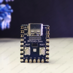
- ESP32-Camera
- TFT Display ST7735
- FTDI Module (recommended: ESP32-CAM-MB)
- Jumper wire
- Bread Board
Pinout
| ESP32 Camera Pinout |
 |
| TFT Display Pinout |
 |
Circuit Diagram / Wiring
Using the FTDI Adapter
If you choose to use an FTDI adapter, here are the steps to connect it to the ESP32-CAM module.
- CAMERA 5V → 5V (FTDI)
- CAMERA GND → GND (FTDI)
- CAMERA U0R (RX) → TX (FTDI)
- CAMERA U0T (TX) → RX (FTDI)
Boot Mode Selection
- To program the ESP32-CAM, connect GPIO0 to GND. This puts the ESP32-CAM into flash mode.
(You can use a push button or jumper wire for this connection.)

TFT Display With ESP32 Camera
- TFT DISPLAY VCC→ 5V (CAMERA)
- TFT DISPLAY GND → GND (CAMERA)
- TFT DISPLAY BL → 3.3V(CAMERA)
- TFT DISPLAY RST → GPIO 15 (CAMERA)
- TFT DISPLAY CS → GPIO 2 (CAMERA)
- TFT DISPLAY D/C → GPIO 12 (CAMERA)
- TFT DISPLAY DIN → GPIO 13 (CAMERA)
- TFT DISPLAY CLK → GPIO 14 (CAMERA)

Programming the ESP32-CAM
Installing the ESP32 Board
To use the ESP32-CAM, or any ESP32, with the Arduino IDE, you must first install the ESP32 board package (also known as the ESP32 Arduino Core) through the Arduino Board Manager.
If you haven’t already, follow this tutorial to install the ESP32 board
Selecting the Board and Port
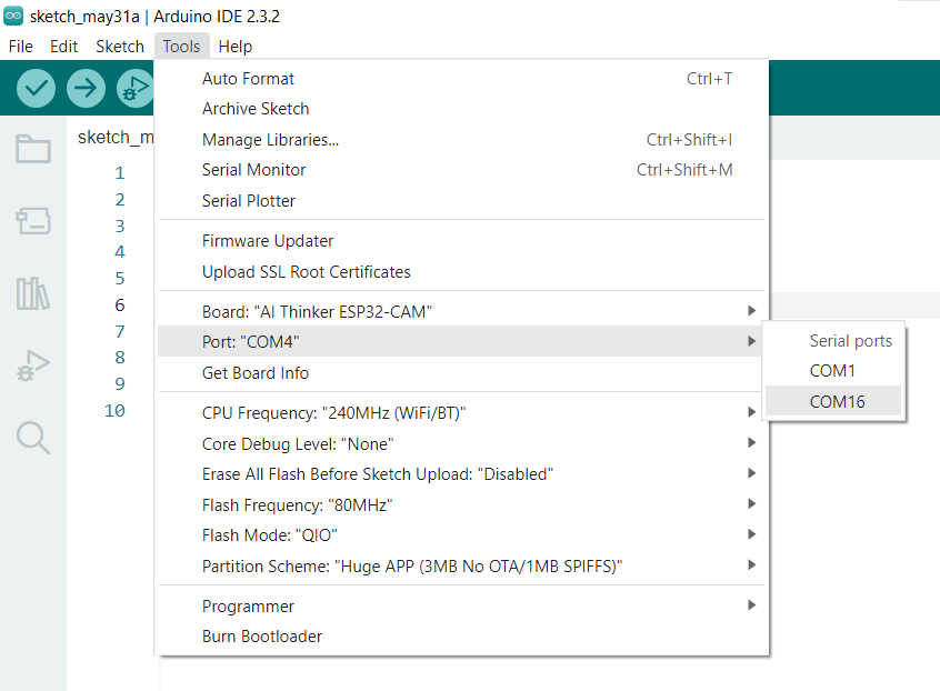
Once the ESP32 Arduino Core is installed, restart your Arduino IDE. Then, go to Tools > Board > ESP32 Arduino and choose AI-Thinker ESP32-CAM from the list.

Now, connect the ESP32-CAM to your computer using a USB cable. Then, go to Tools > Port and select the COM port that the ESP32-CAM is connected to.
CODE

Comment (1)