Index

Introduction
The ESP32-C3-Mini is a compact and powerful module developed by Espressif, featuring a RISC-V single-core processor, Wi-Fi, and Bluetooth LE capabilities. Its small size and rich feature set make it ideal for IoT applications, wearable electronics, and other space-constrained projects.
Specifications
| Feature | Description |
| Processor | RISC-V single-core 32-bit processor, up to 160 MHz |
| Wireless Connectivity | 2.4 GHz Wi-Fi 4 and Bluetooth 5 (LE) |
| Memory | 400 KB SRAM, 4 MB Flash |
| Interfaces | UART, I2C, SPI, GPIO, ADC |
| USB | Type-C connector for power and programming |
| Operating Voltage | 3.3V |
| Dimensions | 22x17x5 mm (LxWxH) |
Features
- Low-power SoC equipped with RISC-V 32-bit single-core processor, up to 160MHz main frequency.
- Supports 2.4GHz Wi-Fi (802.11 b/g/n) and Bluetooth® 5 (LE).
- 400KB of SRAM and 384KB ROM, and 4MB of onboard Flash memory.
- Castellated module and onboard ceramic antenna, allow soldering direct to carrier boards.
- Supports flexible clock, module power supply independent setting, and other controls to realize low power consumption in different scenarios.
- Integrated with USB serial port full-speed controller, 15 × GPIO pins allow flexible configuring pin functions.
- 3 × SPI, 1 × I2C, 2 × UART, 1 × I2S, 2 × ADC, etc.
Hardware overview
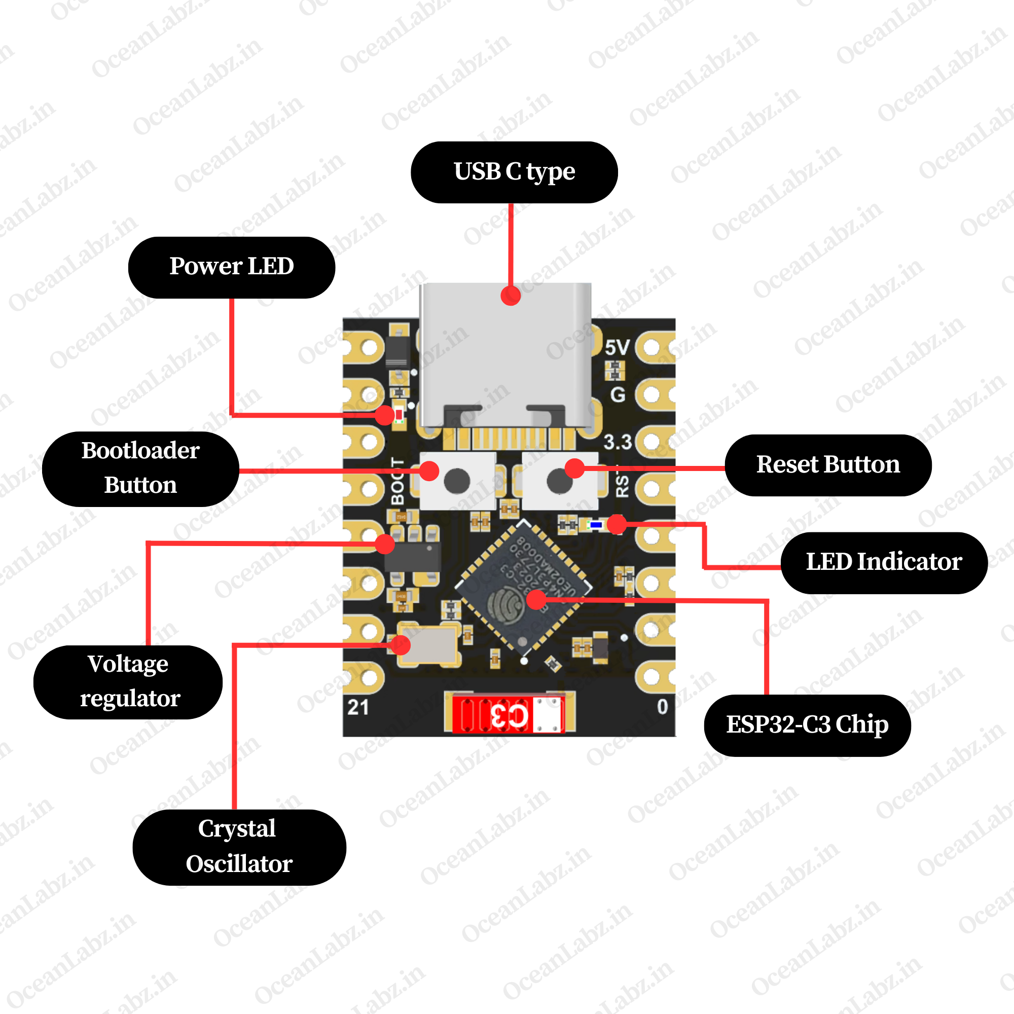
| ESP32C3 Super mini indication diagram |
 |
| ESP32C3 Super mini Pin List |
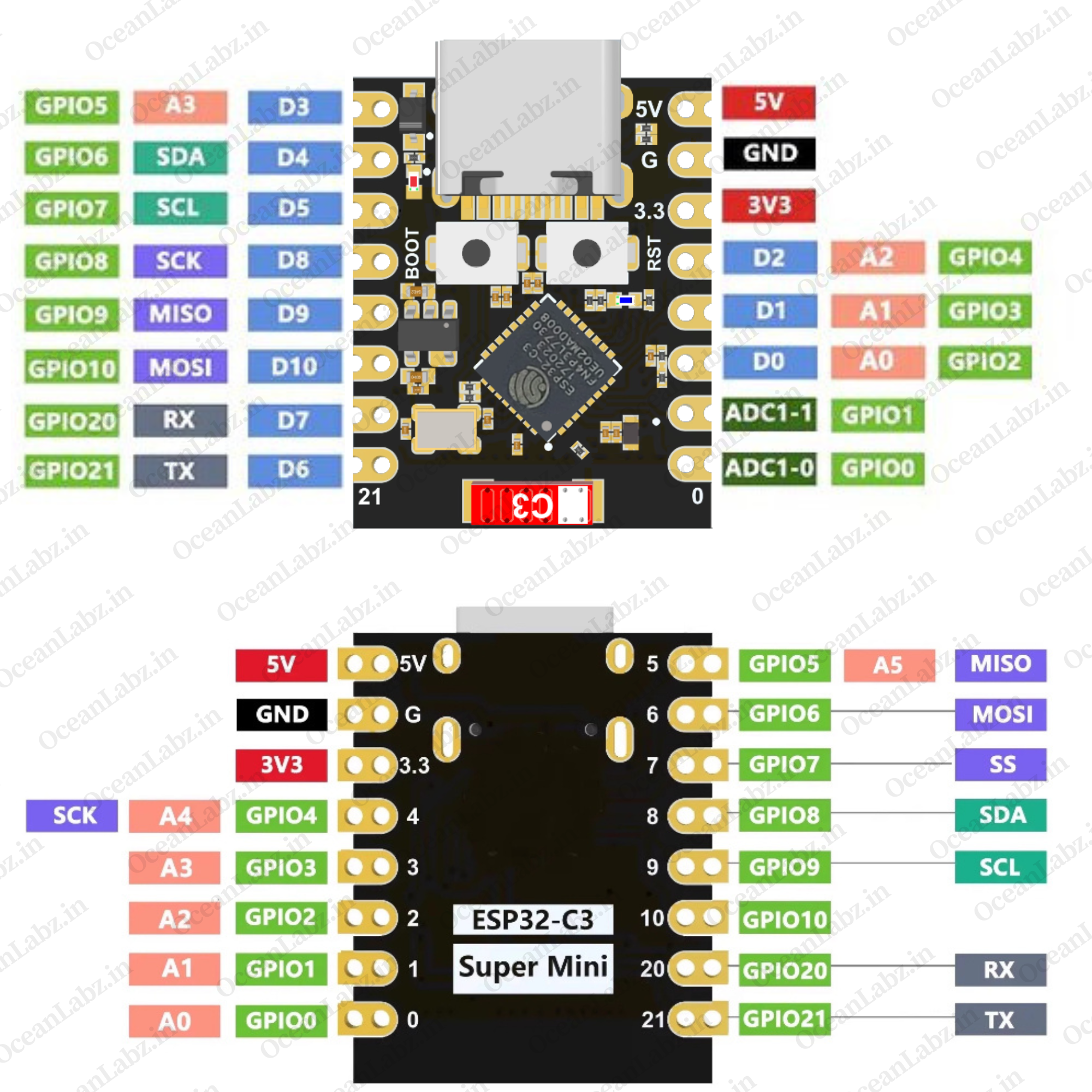 |
| Pinout Description |
| 1. Power Pins: 5V, 3.3V, GND for powering the board. 2. Analog Pins: A0–A4 (GPIO0–GPIO4) for ADC input. 3. Digital Pins: D0–D10 (GPIO0–GPIO10) for general I/O. 4. I2C: SDA (GPIO8), SCL (GPIO9). 5. SPI: SCK (GPIO6), MISO (GPIO4), MOSI (GPIO5), SS (GPIO7). 6. UART: TX (GPIO21), RX (GPIO20). 7. Special Pins: BOOT for flashing, RST for reset. |
Flash Using USB
For the ESP32-C3, the USB peripheral is available, allowing you to flash the binaries without the need for an external USB-to-UART bridge.
- Note: The ESP32-C3 supports only USB CDC and JTAG.
If you are flashing for the first time, you need to get the ESP32-C3 into the download mode manually. To do so, press and hold the BOOT button and then press the RESET button once. After that release the BOOT button.
Getting Started
Hardware Preparation
To begin working with the ESP32-C3-Mini, ensure you have the following:
- ESP32-C3-Mini Module Development Board
- USB Type-C Cable
- Computer with Windows, macOS, or Linux operating system.
Software Preparation
Install Arduino IDE:
- Download and install the latest version of the Arduino IDE.
Add ESP32 Board Support:
- Open Arduino IDE and navigate to
File>Preferences.

- In the “Additional Boards Manager URLs” field, enter:
https://raw.githubusercontent.com/espressif/arduino-esp32/gh-pages/package_esp32_index.json

- Click
OK. - Go to the “Board manager” tab on the left-hand side of the screen.
- Click on the “Board Manager” button (Board icon) at the top of the Board tab.
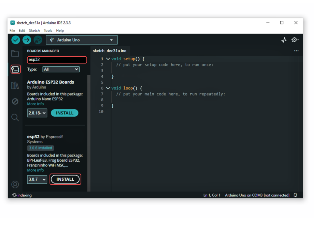
- In the Board Manager window, type “esp32” in the search bar.
- Locate the “esp32” library click on the “Install” button next to it.
- Wait for the board to be installed.
Select the ESP32-C3-Mini Board:
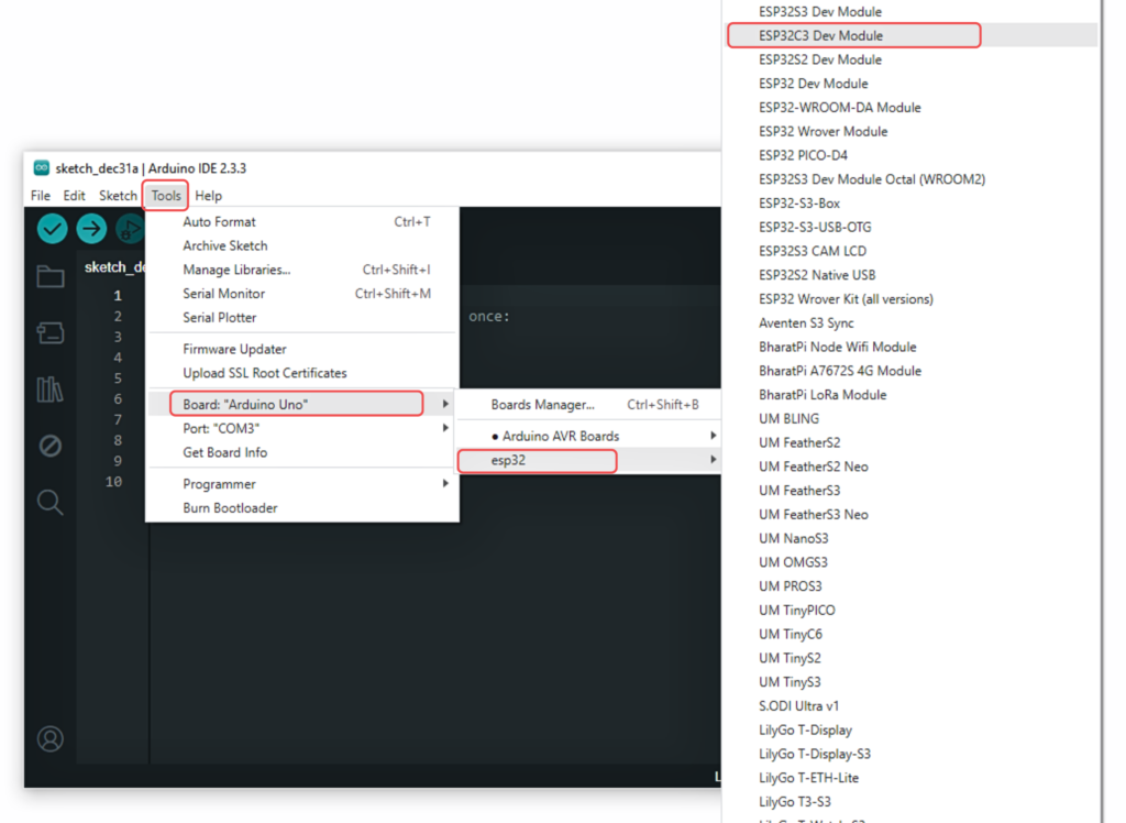
- In Arduino IDE, go to
Tools>Boardand select “ESP32C3 Dev Module” or the appropriate option for your module.
Install USB Drivers:
- Ensure that the necessary USB drivers are installed for your operating system to recognize the ESP32-C3-Mini.
Running Your First Program
Let’s upload a simple “Blink” program to test the setup:
- Connect the ESP32-C3-Mini to Your Computer:
- Use the USB Type-C cable to connect the module.
- Open the Blink Example:
- In Arduino IDE, go to
File>Examples>01.Basics>Blink.
- In Arduino IDE, go to

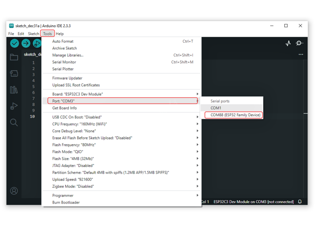
- Configure the Settings:
- Select the correct board and port under the
Toolsmenu.
- Select the correct board and port under the
- Upload the Program:
- Click the
Uploadbutton. - Once uploaded, the onboard LED should start blinking, indicating a successful upload.
- Click the
Power Management and Sleep Modes
The ESP32-C3-Mini supports various power-saving modes, including light sleep and deep sleep, to optimize energy consumption for battery-powered applications.
Deep Sleep Mode
In deep sleep mode, the module achieves minimal power consumption by shutting down most of its components.
Example: Deep Sleep with Timer Wake-Up
void setup() {
  // Configure the wake-up source as timer
  esp_sleep_enable_timer_wakeup(10 * 1000000); // Wake up after 10 seconds
  // Enter deep sleep mode
  esp_deep_sleep_start();
}

void loop() {
  // This will not be reached after deep sleep
}
In this example, the ESP32-C3-Mini enters deep sleep mode and wakes up after 10 seconds due to the timer wake-up source.


Comments (7)