Index
Overview
This project demonstrates how to integrate an ESP32-CAM module with a 1.8″ TFT SPI 128×160 display module to display static information or graphics. This setup can be used for various applications like displaying sensor data, simple graphics, or status messages.
Used Part
ESP32 CAM

The ESP32 CAM is a powerful little board that combines a Wi-Fi microcontroller with a built-in camera. This makes it perfect for creating internet-connected camera projects. Here’s a quick intro to getting started:
Display Module

The 1.8″ TFT SPI 128×160 Display Module is a compact and versatile display solution for various electronic projects. It features a 1.8-inch TFT LCD screen with a resolution of 128×160 pixels, driven via SPI communication, making it easy to interface with microcontrollers like Arduino, ESP32, and Raspberry Pi.
Circuit Diagram
Connect the Display Module to ESP32-CAM:
| Display PIN | ESP32 CAM PIN |
| VCC | 5 V |
| GND | GND |
| CS | GPIO 13 |
| RST | GPIO 15 |
| DC | GPIO 14 |
| DIN | GPIO 12 |
| CLK | GPOI 2 |
| BL | 3.3 V |

Programming the ESP32-CAM
Programming the ESP32-CAM can be somewhat challenging because it doesn’t have a built-in USB port. As a result, users need additional hardware to upload programs from the Arduino IDE. While this isn’t overly complicated, it is inconvenient.
To program this device, you will need either a USB-to-serial adapter (such as an FTDI adapter) or an ESP32-CAM-MB programmer adapter.
Using the FTDI Adapter
If you choose to use an FTDI adapter, here are the steps to connect it to the ESP32-CAM module.
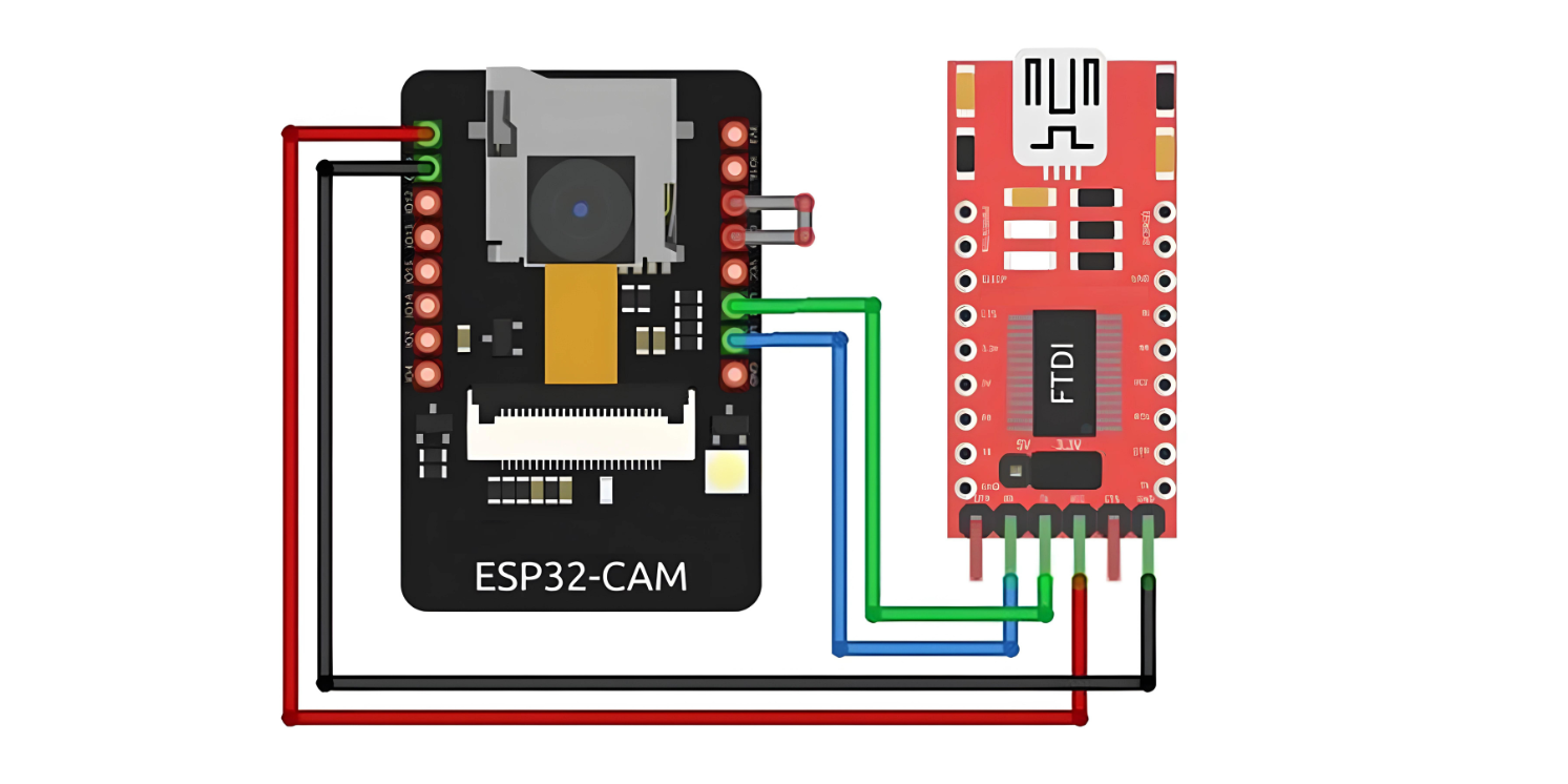
Many FTDI programmers feature a jumper to select between 3.3V and 5V. Since we are powering the ESP32-CAM with 5V, ensure the jumper is set to 5V.
Using the ESP32-CAM-MB Adapter (Recommended)
Programming the ESP32-CAM with an FTDI Adapter can be cumbersome. Therefore, many vendors now offer the ESP32-CAM board with an additional small daughterboard known as the ESP32-CAM-MB.
To program your ESP32-CAM, simply stack it onto the daughterboard, connect a micro USB cable, and click the Upload button. It’s as easy as that.
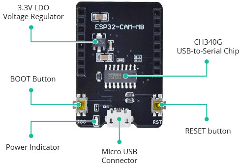
The standout feature of this board is the CH340G USB-to-Serial converter, which handles data transfer between your computer and the ESP32-CAM. Additionally, it includes a RESET button, a BOOT button, a power indicator LED, and a voltage regulator to provide ample power to the ESP32-CAM.
