Index
Introduction
Arduino is not a microcontroller itself, but it is a platform that uses a microcontroller as its core component. An Arduino board typically consists of a microcontroller, voltage regulator, and some input/output pins that are used to interface with various sensors, actuators, and other electronic components. The microcontroller used in Arduino boards can vary, but most commonly it is an Atmel AVR microcontroller. So in short, an Arduino board is a microcontroller development board that uses a microcontroller as its core component. Arduino boards are designed to be easy to use and can be programmed using a simplified version of the C++ programming language.
Hardware Overview
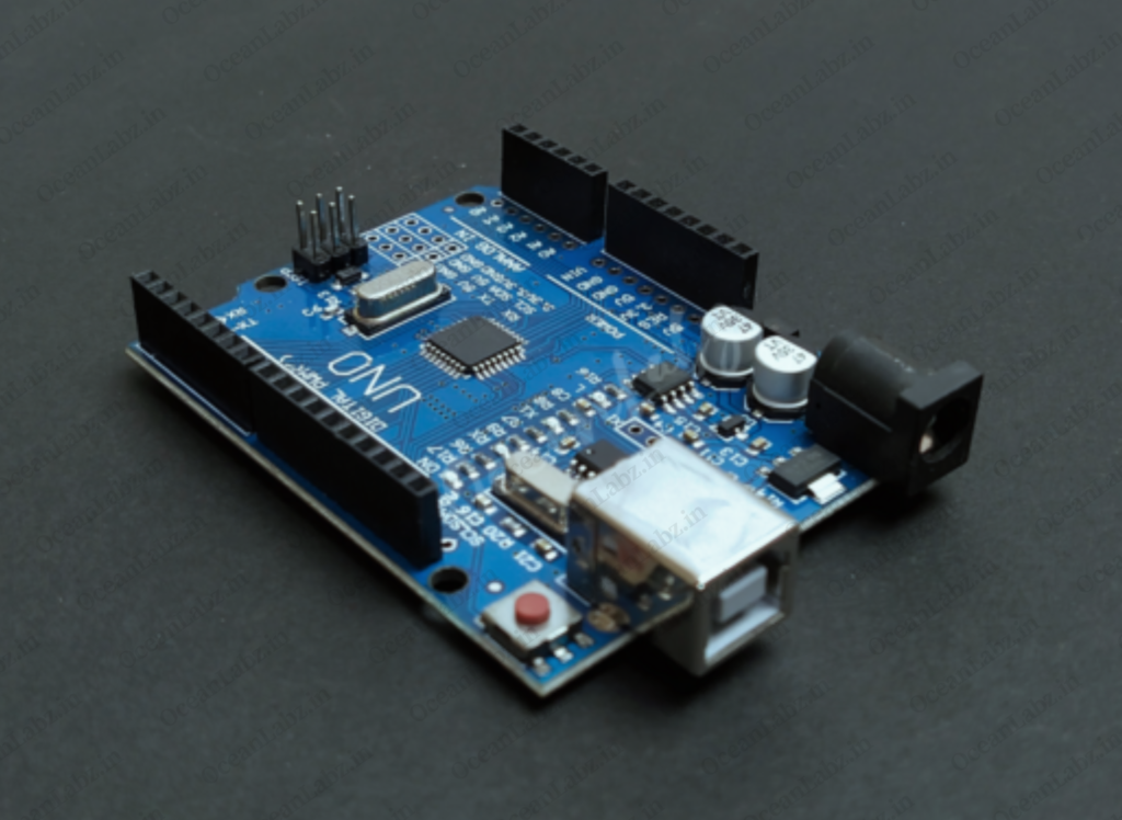
The Arduino Uno R3 SMD (Surface Mount Device) version is essentially the same as the standard Arduino Uno R3, but it uses surface mount components instead of through-hole components for some parts of the board’s construction. Here’s an overview of the hardware features of the Arduino Uno R3 SMD:
Microcontroller:

- The Arduino Uno R3 SMD is based on the ATmega328P microcontroller, an 8-bit AVR microcontroller from Microchip Technology.
- It operates at a clock speed of 16 MHz and has 32 KB of Flash memory, 2 KB of SRAM, and 1 KB of EEPROM.
Power Supply:

- The Arduino Uno R3 SMD can be powered via USB connection or an external power source connected to the Vin pin, supporting an input voltage range of 7 to 12 volts.
- It provides 5V and 3.3V regulated power outputs, along with Ground (GND) pins for connecting external components.
LEDs and Reset Button:

- LEDs: Provide visual feedback and debugging assistance.
- Reset Button: Allows for quick restarts of the microcontroller.
- CH340: USB-to-serial chip facilitating communication with a computer via USB.
Features
- Microcontroller: ATmega328P with 32KB flash memory and 2KB SRAM
- Digital I/O Pins: 14 pins, 6 PWM capable
- Analog Inputs: 6 channels
- Clock Speed: 16MHz
- Voltage Regulator: 5V
- USB Interface: for programming and communication
- Reset Button: for restarting the microcontroller
- LEDs: for power and status indication
- Compatibility: with shields and libraries
- Open-Source Platform: for customization
- Compact Form Factor: portable and embedded use
Technical Specifications
here are some technical details about the Arduino Uno board:
- Microcontroller: The Arduino Uno is based on the ATmega328P microcontroller.
- Clock speed: The microcontroller runs at a clock speed of 16 MHz.
- Flash memory: The ATmega328P has 32 KB of flash memory, of which 0.5 KB is used by the bootloader.
- SRAM: The microcontroller has 2 KB of SRAM.
- EEPROM: The ATmega328P has 1 KB of EEPROM.
- Power: The board can be powered using a USB cable, a DC power jack, or an external power source connected to the Vin pin.
- Input voltage: The input voltage range is 7-12V DC, but the board can also be powered by a 5V DC input.
- Reset button: The board has a reset button, which can be used to restart the program running on the microcontroller.
- LED: The board has a built-in LED connected to pin 13, which can be used for debugging purposes.
Application
- Prototyping and DIY Projects: Quick development of interactive electronic projects.
- Education: Teaching electronics and programming concepts in schools and universities.
- Home Automation: Controlling lighting, heating, and appliances for smart home systems.
- Robotics: Powering and controlling various types of robots.
- IoT Projects: Connecting sensors to the internet for data monitoring and analysis.
- Environmental Monitoring: Measuring parameters like temperature and air quality.
- Art Installations: Creating interactive art that responds to human presence or environmental changes.
- Agricultural Automation: Optimizing irrigation and greenhouse systems.
- Industrial Automation: Automating processes and monitoring machine conditions.
Pinout
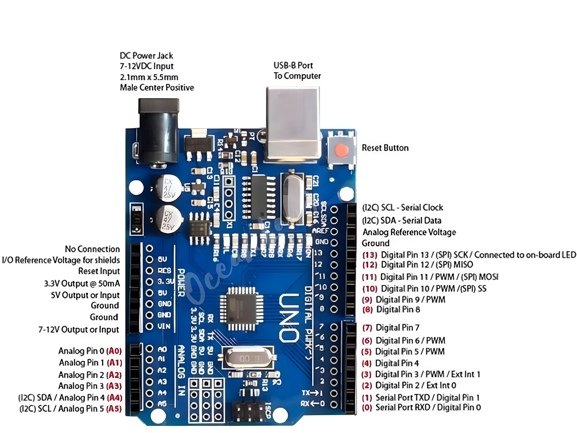
- Digital pins 0-13: These pins can be used as either inputs or outputs, and are typically used for controlling LEDs, reading switches, and so on.
- Analog pins A0-A5: These pins can be used to measure analog voltages.
- Power pins: The board has several power pins, including +5V, +3.3V, and GND.
- PWM pins: Pins 3, 5, 6, 9, 10, and 11 can be used as PWM outputs.
- ICSP header: This header is used for programming the microcontroller using an in-circuit programmer.
- UART pins: Pins 0 (RX) and 1 (TX) are used for the hardware UART serial port.
- I2C pins: Pins A4 (SDA) and A5 (SCL) are used for the hardware I2C interface.
- SPI pins: Pins 10 (SS), 11 (MOSI), 12 (MISO), and 13 (SCK) are used for the hardware SPI interface.
Programming the Arduino
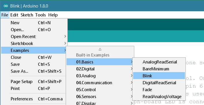
Step 1: Open your first sketch
- Open the LED blink example sketch: File > Examples >01.Basics > Blink.
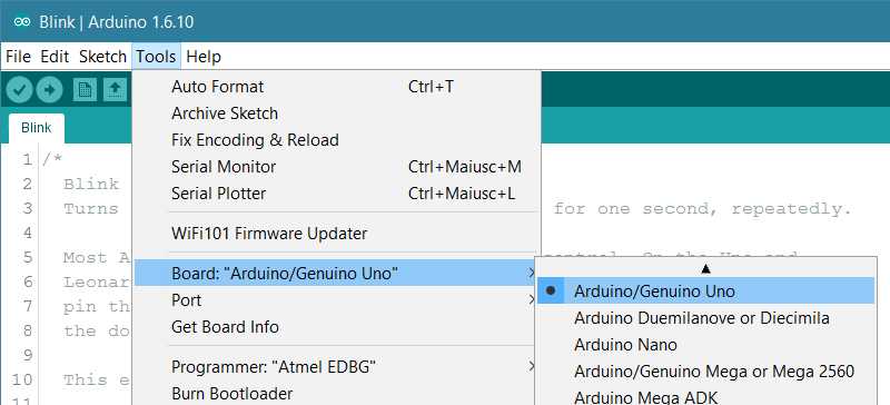
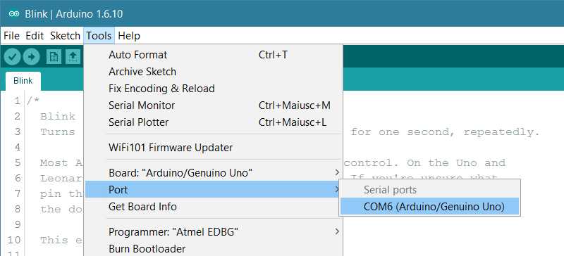
Step 2: Select your board type and port
- You’ll need to select the entry in the Tools > Board menu that corresponds to your Arduino board.
Select the serial device of the board from the Tools | Serial Port menu. This is likely to be COM3 or higher (COM1 and COM2 are usually reserved for hardware serial ports). To find out, you can disconnect your board and re-open the menu; the entry that disappears should be the Arduino board. Reconnect the board and select that serial port.
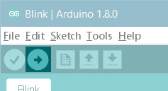
Step 3: Upload the program
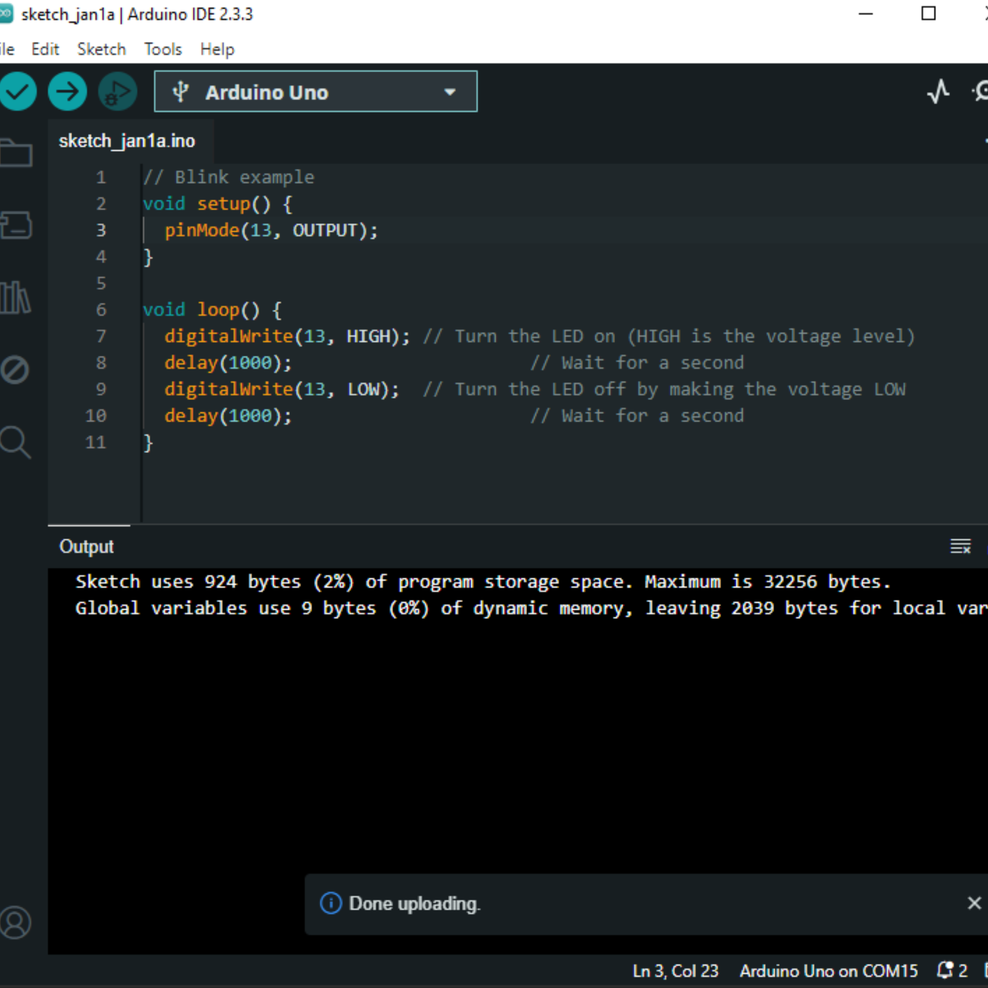
- Copy the provided code into your Arduino IDE.
// Blink example
void setup() {
  pinMode(13, OUTPUT);
}

void loop() {
  digitalWrite(13, HIGH); // Turn the LED on (HIGH is the voltage level)
  delay(1000);                      // Wait for a second
  digitalWrite(13, LOW);  // Turn the LED off by making the voltage LOW
  delay(1000);                      // Wait for a second
}
Now, simply click the “Upload” button in the environment. Wait a few seconds – you should see the RX and TX leds on the board flashing. If the upload is successful, the message “Done uploading.” will appear in the status bar.
A few seconds after the upload finishes, you should see the pin 13 (L) LED on the board start to blink (in orange). If it does, congratulations! You’ve gotten Arduino up-and-running.
 |  |

