Index

Introduction
The Arduino Nano is a compact and versatile microcontroller board based on the ATmega328P microcontroller chip. It is similar to the Arduino Uno but offers a smaller form factor, making it suitable for projects with space constraints. Despite its small size, the Nano retains the key features of the Uno, including digital and analog I/O pins, PWM outputs, UART, SPI, and I2C interfaces, as well as USB connectivity for programming and power. The Nano is widely used in various electronics projects, from robotics and automation to IoT devices and wearable technology, due to its ease of use, affordability, and compatibility with the Arduino ecosystem.
Hardware Overview

Microcontroller: The Nano is powered by the ATmega328P microcontroller chip, which provides processing capabilities for running Arduino sketches and interfacing with various peripherals.
USB Interface: The Nano includes a USB interface for programming the board and communication with a computer. It uses a mini-USB or micro-USB connector, depending on the version.

Reset Button: A reset button allows you to restart the microcontroller or reset the running program when needed.
The ICSP: (In-Circuit Serial Programming) header on the Arduino Nano facilitates programming and debugging of the microcontroller using an external programmer/debugger. It comprises six pins: MOSI, MISO, SCK, RESET, VCC, and GND. These pins handle data transmission, clock signal, reset functionality, and power supply connection, enabling advanced programming operations beyond the standard USB interface.

Voltage Regulator: Equipped with a built-in voltage regulator, the Nano can accept a wide range of input voltages (typically 7-12V) and provide a stable 5V output for powering the board and connected components.
The CH340G: is a USB-to-serial chip commonly used in Arduino Nano boards to provide USB connectivity for communication with a computer. It converts USB signals to serial signals, allowing the Nano to communicate with the computer via USB. This chip enables programming and serial communication over USB, making it a crucial component for connecting the Nano to a computer for development and debugging purposes.
Features
- Microcontroller: ATmega328P with 32KB flash memory and 2KB SRAM.
- Digital I/O Pins: 14 digital input/output pins, 6 of which support PWM output.
- Analog Inputs: 8 analog input pins for reading sensors or signals.
- Clock Speed: 16MHz, providing fast instruction execution.
- USB Interface: Includes a micro USB interface for easy programming and communication with a computer.
- Power Supply: Can be powered via USB or an external power supply (7-12V recommended).
- Reset Button: Provides a reset button for restarting the microcontroller or resetting the program.
- Built-in LEDs: Includes power and status LEDs, with an onboard LED connected to pin 13.
- Compact Size: Small form factor, making it suitable for portable and embedded projects.
- Compatibility: Compatible with a wide range of shields and libraries, expanding its capabilities.
- CH340: Utilizes the CH340 USB-to-serial chip for USB communication and programming.
Application
- Prototyping: Ideal for quick prototyping of electronic projects and proof-of-concept designs.
- Wearable Electronics: Suitable for wearable devices due to its small form factor.
- Robotics: Used in small robotics projects, including simple robots, automated vehicles, and robotic arms.
- Home Automation: Can be employed in home automation systems to control lights, security systems, and other appliances.
- IoT Projects: Serves as a core component in Internet of Things (IoT) projects for sensing and controlling various parameters.
- Embedded Systems: Utilized in embedded systems for various applications, from consumer electronics to industrial automation.
- Educational Purposes: Widely used in educational environments to teach electronics, programming, and embedded systems.
- DIY Projects: Popular in DIY electronics projects for hobbyists and makers.
Technical Specifications
- Type: Development Board Module
- Microcontroller: ATmega328P
- Voltage: 5V
- Clock Speed: 16 MHz
- Digital I/O Pins: 14 (6 PWM)
- Analog Input Pins: 8
- Memory: 32 KB Flash, 2 KB SRAM, 1 KB EEPROM
- Communication: USB, UART, SPI, I2C
- Power Supply: USB or 7V-12V external
- Programming: Arduino IDE
- Features: Compact, USB programming, Arduino Nano compatible
Pinout

Power Pins:
- VIN: Input voltage to the Arduino board when using an external power source (6-12V).
- 5V: Regulated power supply used to power the microcontroller and other components on the board.
- 3.3V: A 3.3V supply generated by the onboard regulator. Maximum current draw is 50 mA.
- GND: Ground pins.
Analog Pins:
- A0-A7: Analog inputs, which can also be used as digital pins (A6 and A7 can only be used as analog inputs).
Digital I/O Pins:
- D0-D13: Digital input/output pins.
- D2-D13: Can also be used as PWM outputs.
Special Pins:
- TX (D1): Transmit pin for serial communication.
- RX (D0): Receive pin for serial communication.
- SCL (A5): Clock line for I2C communication.
- SDA (A4): Data line for I2C communication.
- AREF: Reference voltage for the analog inputs.
- RST: Can be used to reset the microcontroller.
ICSP Header:
- Used for programming the Arduino and connecting peripherals like sensors and displays.
- Contains MISO, MOSI, SCK, RESET, VCC, and GND.
CH340G:
- USB-to-serial converter chip, used for communication between the Arduino and the computer.
Programming the Arduino Nano
Step 1: Install the Arduino IDE
- Download and install the Arduino IDE from the official Arduino website.
- Follow the installation instructions specific to your operating system.
Step 2: Connect the Arduino Nano to Your Computer
- Use a USB cable (Mini USB) to connect the Arduino Nano to your computer.
Step 3: Select the Board and Port
- Open the Arduino IDE.
- Go to
Tools>Boardand selectArduino Nano.

- Go to
Tools>Portand select the COM port to which your Arduino Nano is connected.

- Go to
Tools>Processorand choose the correct processor (ATmega328PorATmega328P (Old Bootloader)) depending on your Nano version.
Step 4: Upload The Code
- Copy the provided code into your Arduino IDE.
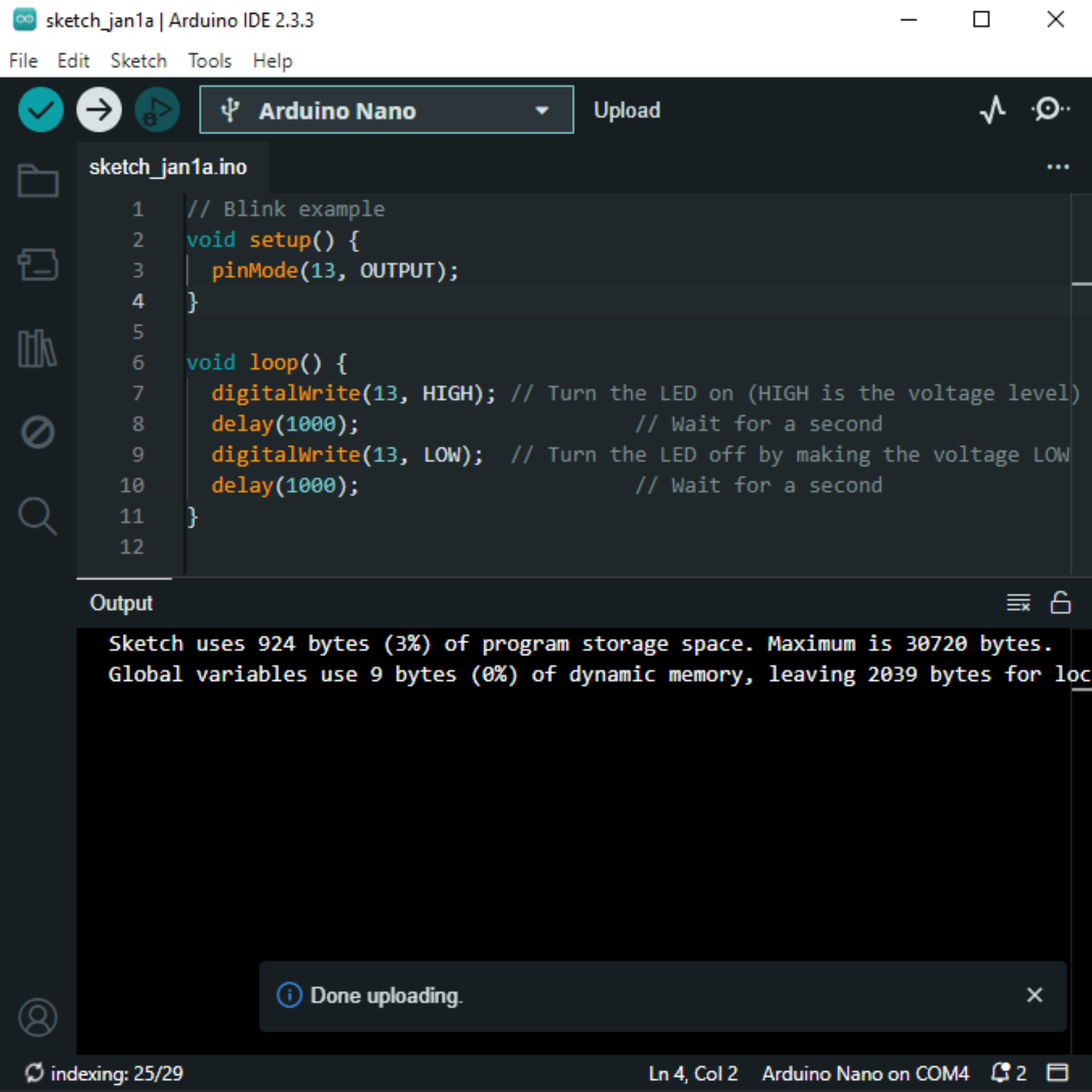
// Blink example
void setup() {
  pinMode(13, OUTPUT);
}

void loop() {
  digitalWrite(13, HIGH); // Turn the LED on (HIGH is the voltage level)
  delay(1000);                      // Wait for a second
  digitalWrite(13, LOW);  // Turn the LED off by making the voltage LOW
  delay(1000);                      // Wait for a second
}
- Alternatively, you can load an example sketch by going to
File>Examples>01.Basics>Blink - Verify and upload the code to your Arduino board.

Notes:
- Ensure you have the correct drivers installed for the CH340 USB-to-serial converter if your Arduino Nano uses it.
- If you encounter issues with uploading, try selecting
ATmega328P (Old Bootloader)underTools>Processor.
 |  |
Troubleshooting Steps
- Computer Recognition:
- Check USB cable and port.
- Verify COM port selection.
- Install CH340 driver if needed.
- Upload Errors:
- Confirm correct board and processor selection.
- Reset Nano before upload.
- Reinstall USB drivers if required.
- Sketch Issues:
- Debug code for errors.
- Match Serial Monitor baud rate.
- Ensure sufficient power supply.
- Unresponsive Board:
- Try resetting Nano.
- Flash bootloader if needed.
- Compilation Errors:
- Fix code syntax or logic.
- Verify library installations.
Additional Tips:
- Visit Arduino forums.
- Test different USB ports.
- Check for physical damage on Nano.

