Index

The ESP32 CAM is a powerful little board that combines a Wi-Fi microcontroller with a built-in camera. This makes it perfect for creating internet-connected camera projects. Here’s a quick intro to getting started:
Hardware Overview
The core of the ESP32-CAM is the ESP32-S System-on-Chip (SoC) from Ai-Thinker. As an SoC, the ESP32-S includes a complete computer system, comprising a microprocessor, RAM, storage, and peripherals, all integrated into a single chip. Although the chip itself boasts impressive capabilities, the ESP32-CAM development board enhances these features further. Let’s examine each component individually.
- ESP32 S-Processor
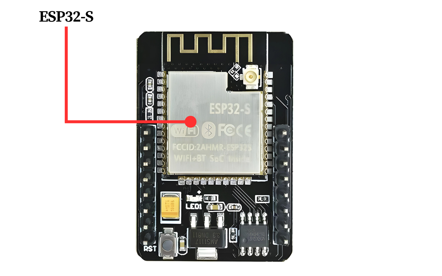
The ESP32-CAM features the ESP32-S surface-mount module from Ai-Thinker. This module is similar in form factor and general specifications to Espressif’s ESP-WROOM-32 module. At the heart of the ESP32-S is a Tensilica Xtensa® LX6 microprocessor, which boasts two 32-bit cores running at an impressive 240 MHz. This high processing power makes the ESP32-S ideal for demanding tasks such as video processing, facial recognition, and even artificial intelligence applications
- The Memory
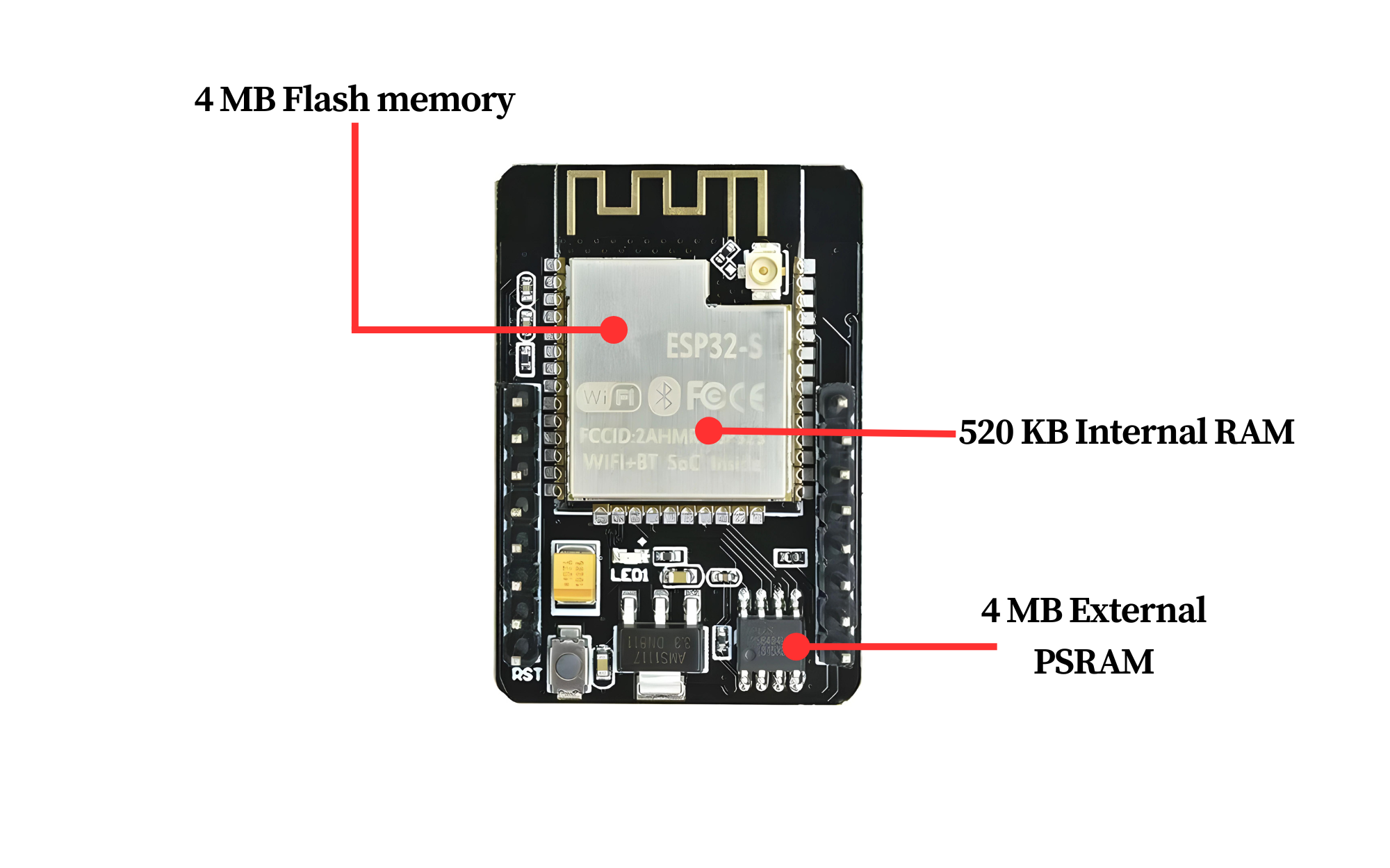
Memory is crucial for handling complex tasks, and the ESP32-S is equipped with 520 kilobytes of internal RAM, integrated on the same die as the rest of the chip’s components.
However, for memory-intensive applications, this might not be sufficient. Therefore, the ESP32-CAM includes 4 MB of external PSRAM (Pseudo-Static RAM) to enhance its memory capacity. This additional RAM is particularly beneficial for demanding tasks such as audio or graphics processing.
Storage is equally important for housing your programs and data. The ESP32-S excels in this area as well, offering 4 MB of on-chip flash memory. This ample storage ensures you have enough space for your applications and data.
- The Camera
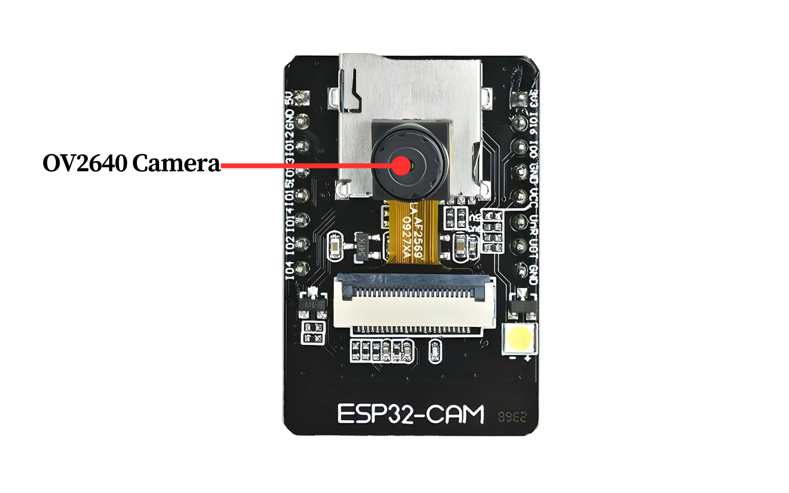
The OV2640 camera sensor integrated into the ESP32-CAM distinguishes it from other ESP32 development boards, making it particularly suitable for video projects such as video doorbells or nanny cams.
The OV2640 camera sensor offers a resolution of 2 megapixels, supporting a maximum resolution of 1600×1200 pixels. This level of resolution is adequate for numerous surveillance applications.
Additionally, the ESP32-CAM is compatible with a variety of camera sensors, as detailed on GitHub.
- The Storage
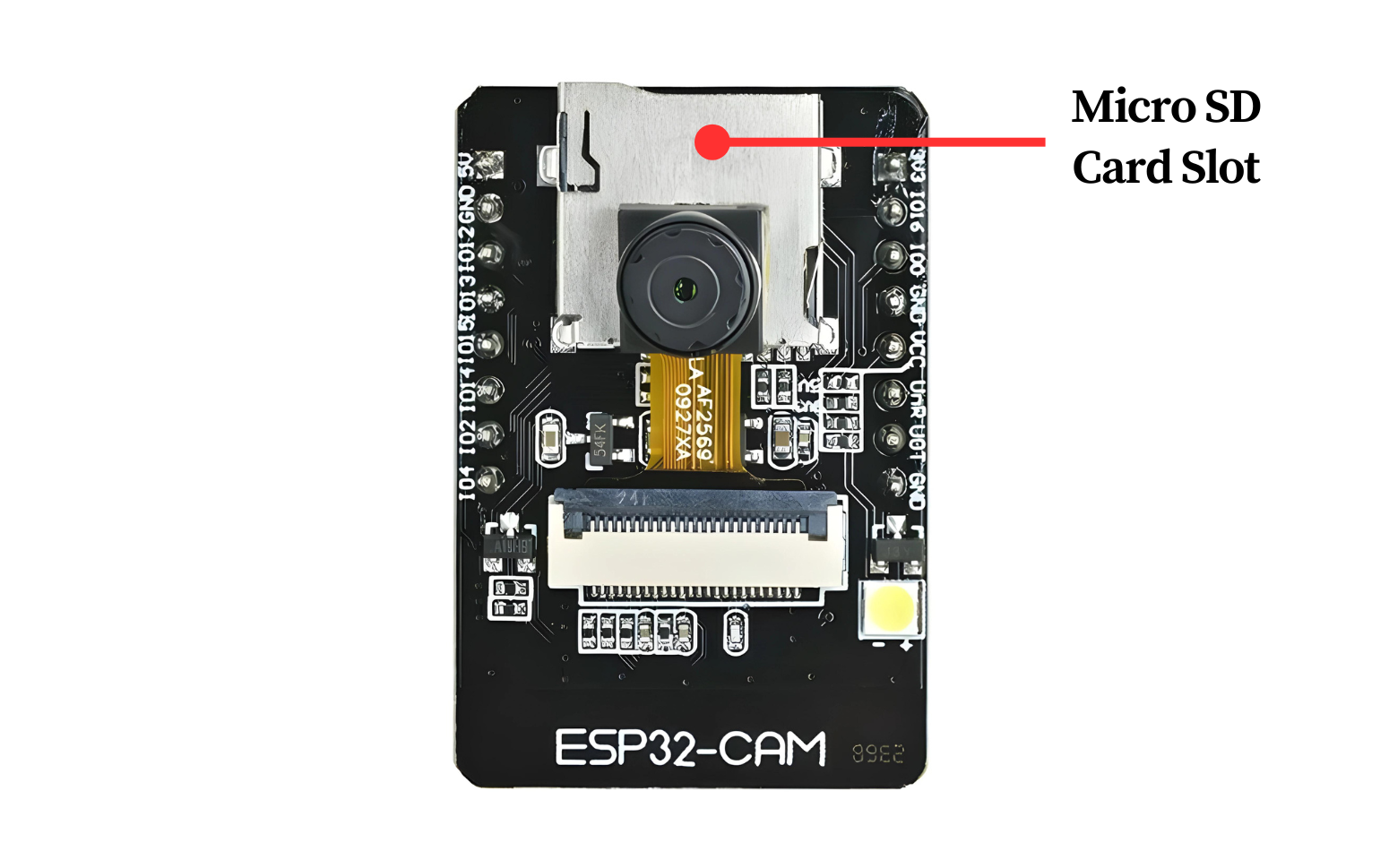
The inclusion of a microSD card slot on the ESP32-CAM is a valuable feature. It provides virtually unlimited storage expansion, making the board an excellent choice for applications such as data logging or image capturing.
- The Antenna
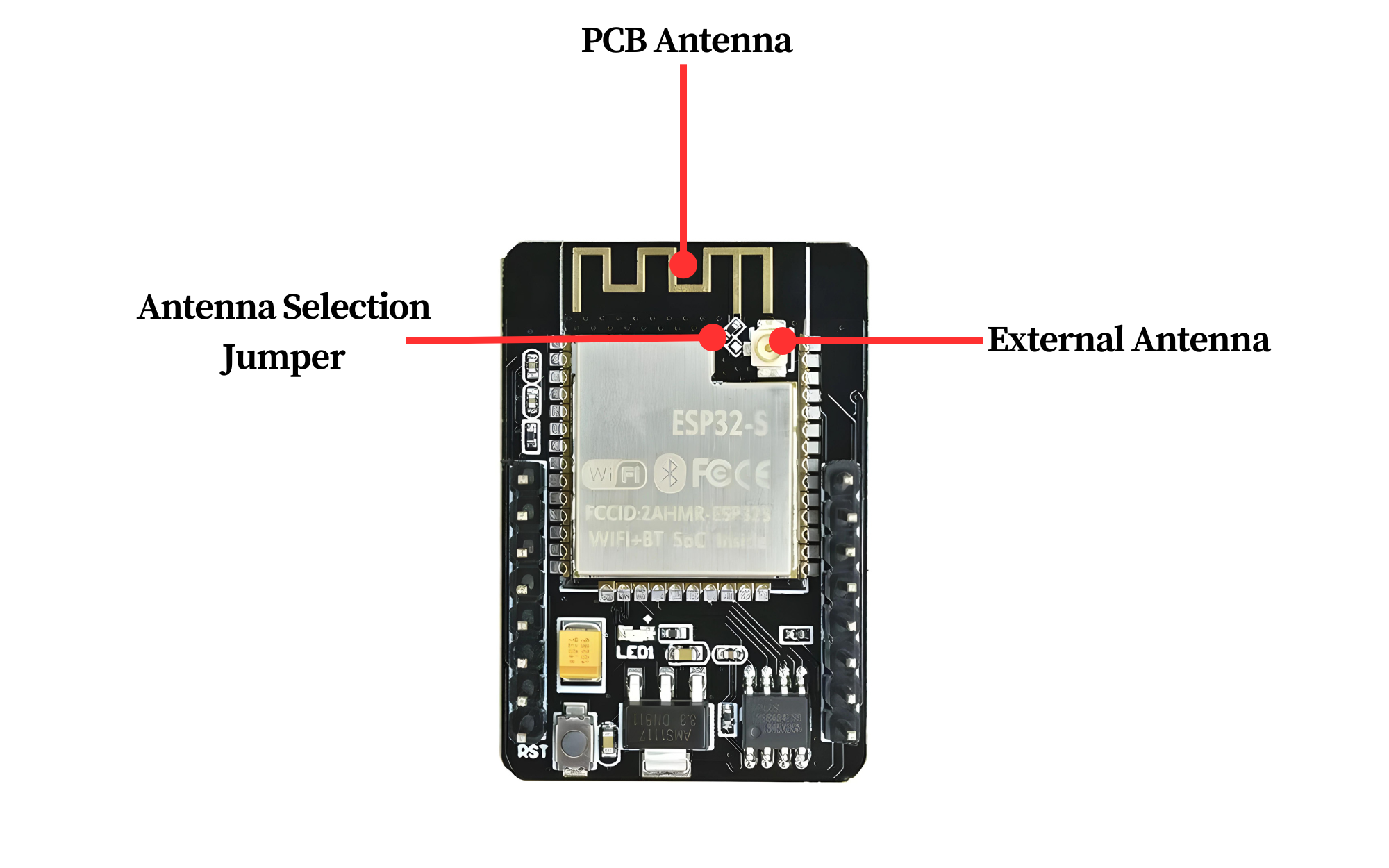
The ESP32-CAM is equipped with an onboard PCB trace antenna and a u.FL connector for an external antenna. You can select between these two options using an Antenna Selection jumper (a zero-ohm resistor).
For instructions on switching from the onboard antenna to an external one, see the guide on connecting an external antenna to the ESP32-CAM.
- LED’s
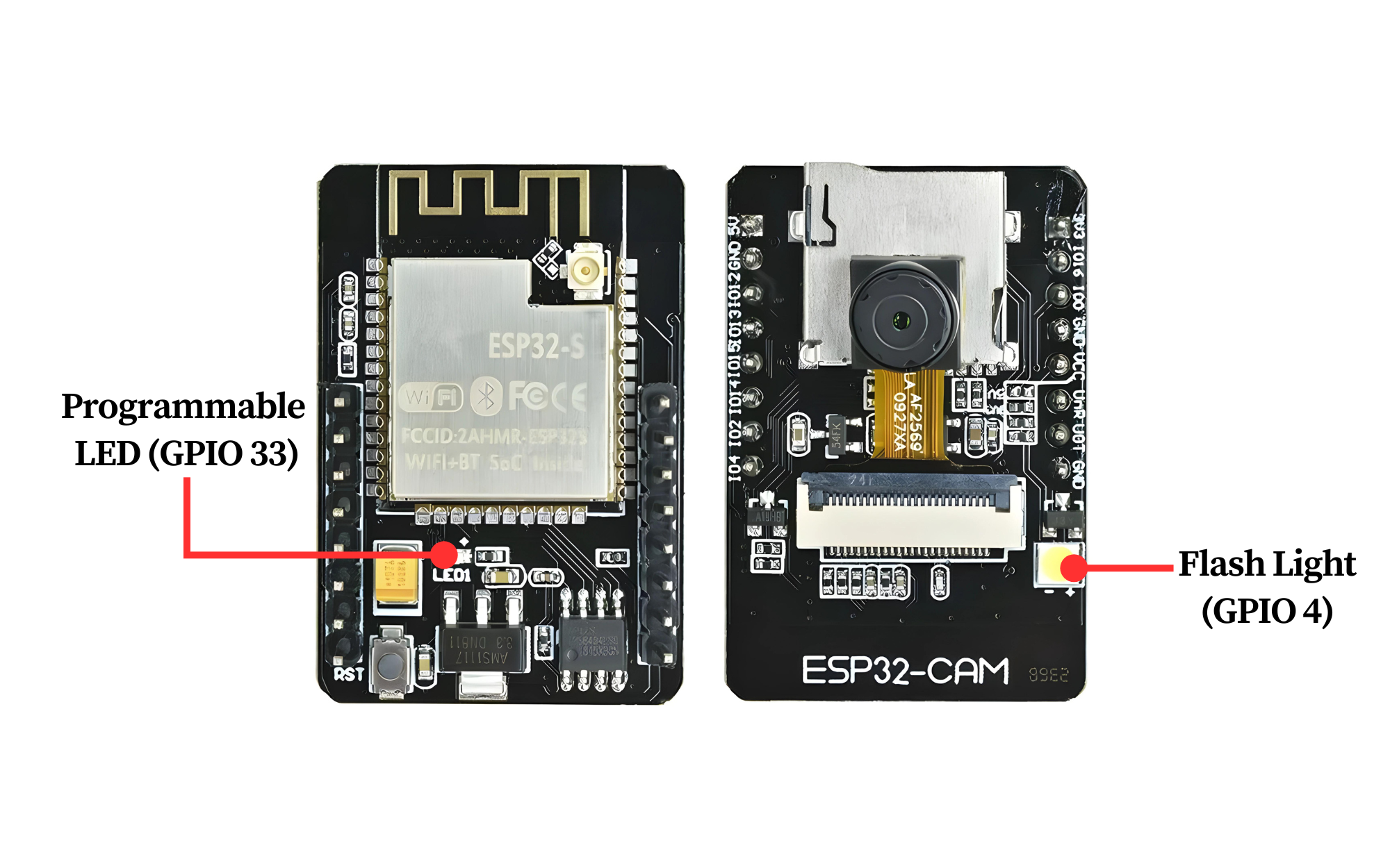
The ESP32-CAM features a white square LED, primarily designed to function as a camera flash, but it can also serve as a general-purpose light source.
Additionally, there is a small red LED on the back of the board, which can be used as a status indicator. This LED is user-programmable and connected to GPIO33.
Technical Specifications
Here are the technical specifications of the ESP32-CAM:
Microcontroller
- Chip: ESP32-S from Ai-Thinker
- CPU: Dual-core Tensilica LX6 microprocessor
- Clock Speed: Up to 240 MHz
- Flash Memory: 4 MB
- SRAM: 520 KB
- PSRAM: 4 MB (Pseudo-Static RAM)
Camera
- Camera Model: OV2640
- Resolution: 2 megapixels
- Image Output: 1600×1200 pixels maximum
Connectivity
- Wi-Fi: 802.11 b/g/n
- Bluetooth: v4.2 BR/EDR and BLE
Interfaces
- GPIO Pins: Multiple General Purpose Input/Output pins
- I2C: Two-wire Interface
- SPI: Serial Peripheral Interface
- UART: Universal Asynchronous Receiver-Transmitter
- ADC: Analog-to-Digital Converter
- DAC: Digital-to-Analog Converter
Power
- Input Voltage: 5V
- Operating Voltage: 3.3V
Additional Features
- Dimensions: Compact form factor suitable for embedded applications
- Weight: Lightweight, ideal for portable devices
ESP32-CAM Power Consumption
The power consumption of the ESP32-CAM varies depending on its operational state and the specific tasks it is performing. Here are some general power consumption metrics:
General Power Consumption Metrics
- Deep Sleep Mode: ~10 µA
- Light Sleep Mode: ~0.8 mA
- Modem Sleep Mode: ~10 mA
- Active Mode (Wi-Fi): ~80-260 mA (varies based on transmission power, data rate, and other factors)
- Active Mode (Camera Streaming): ~160-260 mA (depending on Wi-Fi activity and other peripheral usage)
ESP32 CAM Pinout
The ESP32-CAM development board has various pins that serve different functions. Here’s a basic pinout description:
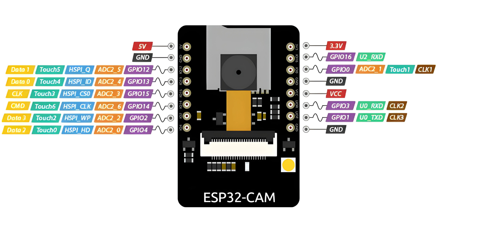
- Power Pins:
- VIN: Input voltage (5V).
- GND: Ground.
- Serial Communication Pins:
- TX: Transmit pin for serial communication.
- RX: Receive pin for serial communication.
- I2C Pins:
- SDA: Data line for I2C communication.
- SCL: Clock line for I2C communication.
- SPI Pins:
- VSPI: SPI pins for external SPI devices.
- HSPI: SPI pins for external SPI devices.
- GPIO Pins:
- General Purpose Input/Output pins for interfacing with external devices or sensors.
- These pins can also be used for PWM, ADC, DAC, etc.
Programming the ESP32-CAM
Programming the ESP32-CAM can be somewhat challenging because it doesn’t have a built-in USB port. As a result, users need additional hardware to upload programs from the Arduino IDE. While this isn’t overly complicated, it is inconvenient.
To program this device, you will need either a USB-to-serial adapter (such as an FTDI adapter) or an ESP32-CAM-MB programmer adapter.
Using the FTDI Adapter
If you choose to use an FTDI adapter, here are the steps to connect it to the ESP32-CAM module.
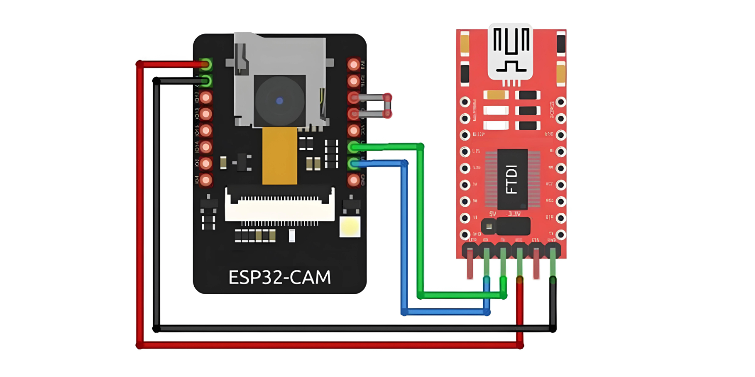
Many FTDI programmers feature a jumper to select between 3.3V and 5V. Since we are powering the ESP32-CAM with 5V, ensure the jumper is set to 5V.
Note that the GPIO 0 pin must be connected to Ground during programming. This connection is required only while uploading code to the ESP32-CAM. After programming, you need to disconnect this connection.
Remember, you’ll need to reconnect GPIO 0 to Ground each time you upload a new sketch.
Using the ESP32-CAM-MB Adapter (Recommended)
Programming the ESP32-CAM with an FTDI Adapter can be cumbersome. Therefore, many vendors now offer the ESP32-CAM board with an additional small daughterboard known as the ESP32-CAM-MB.
To program your ESP32-CAM, simply stack it onto the daughterboard, connect a micro USB cable, and click the Upload button. It’s as easy as that.
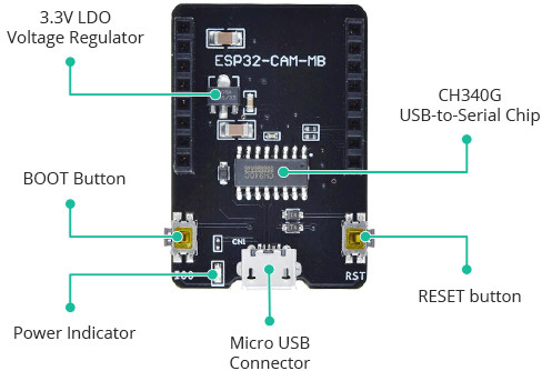
The standout feature of this board is the CH340G USB-to-Serial converter, which handles data transfer between your computer and the ESP32-CAM. Additionally, it includes a RESET button, a BOOT button, a power indicator LED, and a voltage regulator to provide ample power to the ESP32-CAM.
Setting Up the Arduino IDE
Installing the ESP32 Board
To use the ESP32-CAM, or any ESP32, with the Arduino IDE, you must first install the ESP32 board package (also known as the ESP32 Arduino Core) through the Arduino Board Manager.
If you haven’t already, follow this tutorial to install the ESP32 board
Selecting the Board and Port
Once the ESP32 Arduino Core is installed, restart your Arduino IDE. Then, go to Tools > Board > ESP32 Arduino and choose AI-Thinker ESP32-CAM from the list.

Now, connect the ESP32-CAM to your computer using a USB cable. Then, go to Tools > Port and select the COM port that the ESP32-CAM is connected to.
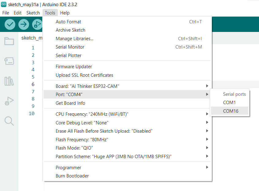
That’s it; the Arduino IDE is now set up for the ESP32-CAM!
ESP32-CAM Example 1 : Blink
After completing the previous steps, you are ready to test your first program with the ESP32-CAM! Open the Arduino IDE. If you disconnected your board, reconnect it.
Let’s upload the most basic sketch of all – Blink!
This sketch utilizes the on-board Camera Flash LED, which is connected to GPIO 4.
int flashPin = 4;

void setup() {
    pinMode(flashPin, OUTPUT);
}

void loop() {
    digitalWrite(flashPin, HIGH);
    delay(1000);
    digitalWrite(flashPin, LOW);
    delay(1000);
}
Next, click the upload button. If you’re using the FTDI adapter, remove the connection between GPIO 0 and GND after the code is uploaded. To run the sketch, you might need to press the Reset button on your ESP32-CAM.
If everything went as expected, the integrated Flash LED on your ESP32-CAM should now be pulsating!
Congratulations! You have just programmed your first ESP32-CAM!

