Index
Introduction
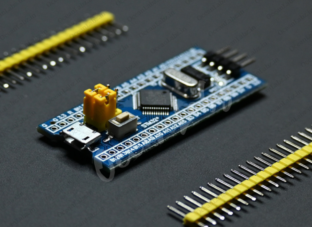
The STM32F103C8T6 is a high-performance microcontroller from STMicroelectronics, part of the STM32F1 series. It is built around the ARM Cortex-M3 32-bit RISC core, offering a balance of high performance, low power consumption, and rich connectivity features. This microcontroller is suitable for a wide range of applications, including industrial control, consumer electronics, and communication equipment. It comes with various peripherals and interfaces, making it a versatile choice for embedded system developers.
Hardware Overview
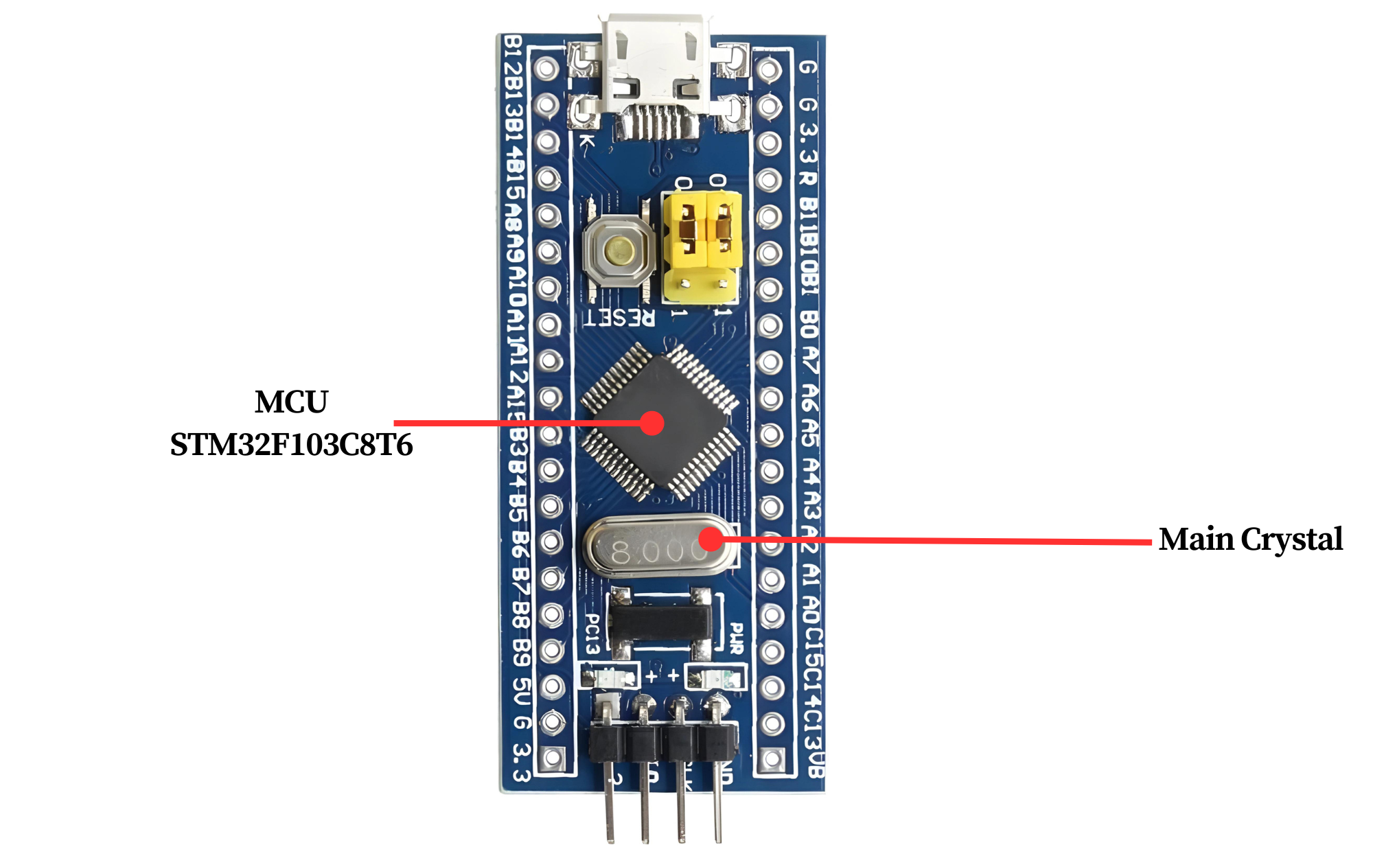
- Microcontroller: A powerful STM32F103C8T6 ARM Cortex-M processor serving as the brain of the board.
- Clock Source: Built-in oscillator or crystal for providing clock signals to the microcontroller.
- Flash Memory: Onboard flash memory for storing program code and data.
- Voltage Requirements: Microcontrollers typically require a specific operating voltage, such as 3.3V or 5V. It’s essential to provide the correct voltage to ensure proper operation and prevent damage.
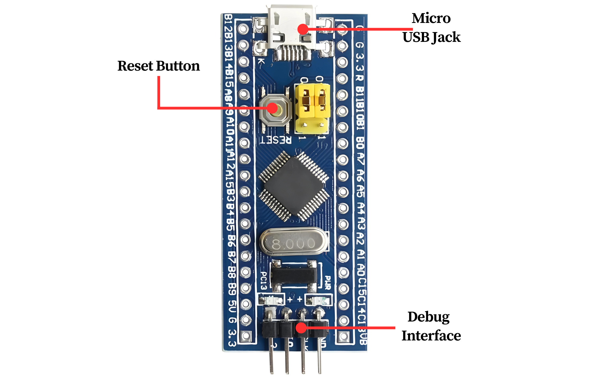
- Reset Circuit: Reset button or circuit for restarting the microcontroller when needed.
- Debug Interface: Debugging and programming interfaces such as SWD (Serial Wire Debug) for development and troubleshooting.
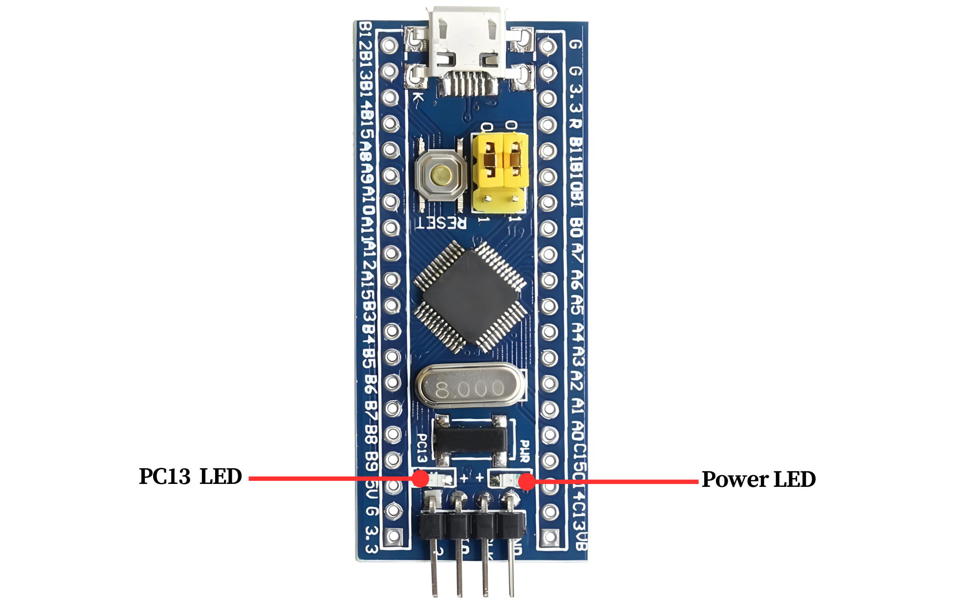
- Power LED: This LED indicates that the device is receiving power and is usually illuminated whenever the device is powered on. It provides a visual indication that the device is operational and receiving the necessary power supply.
- Programming LED: This LED, short for “Programming LED,” is often used in development boards or microcontroller-based systems to indicate when the device is being programmed or programmed successfully. It may blink, flash, or remain steady to provide feedback on the programming process.
Specification
| Specification | Details |
|---|---|
| Microcontroller | STM32F103C8T6 |
| Core | ARM Cortex-M3 running at up to 72 MHz |
| Memory | 64 KB Flash, 20 KB SRAM |
| GPIO | 37 pins |
| Analog Inputs | 10-channel 12-bit ADC |
| Serial Communication | Up to 3 UART, 2 SPI, and 2 I2C interfaces |
| Operating Voltage | 2.0V to 3.6V |
| Operating Temperature | -40°C to +85°C |
Application
- Industrial automation
- Consumer electronics
- Medical devices
- Communication equipment
- Robotics
- Internet of Things (IoT) devices
Pinout

- PA0 to PA15: GPIO Port A (General-Purpose I/O)
- PB0 to PB15: GPIO Port B (General-Purpose I/O)
- PC0 to PC15: GPIO Port C (General-Purpose I/O)
Key pins and their functions:
- PA0 to PA3: Analog input (ADC channels 0 to 3), alternative functions for timers and UART
- PB6 and PB7: I2C1 (Inter-Integrated Circuit) SCL and SDA
- PB10 and PB11: USART3 (Universal Synchronous/Asynchronous Receiver/Transmitter) TX and RX
- PA9 and PA10: USART1 TX and RX
- PA13 and PA14: SWDIO (Serial Wire Debug) and SWCLK (Serial Wire Clock) for debugging and programming
Programming the STM32F103C8T6
Step 1: Install Arduino IDE
- Download the latest version of Arduino IDE from the official website.
- Install the IDE on your computer.
Step 2: Install Required Drivers
Install the ST-Link/V2 or USB Serial drivers depending on your upload method:
- For ST-Link: Download the ST-Link Utility from ST’s official website.
- For USB Serial (CH340 or FTDI): Install the appropriate USB-to-serial drivers.
Step 3: Add STM32 Board Manager to Arduino IDE
- Open the Arduino IDE.
- Go to File > Preferences.

- In the “Additional Board Manager URLs” field, add the following URL:
https://github.com/stm32duino/BoardManagerFiles/raw/main/package_stmicroelectronics_index.json
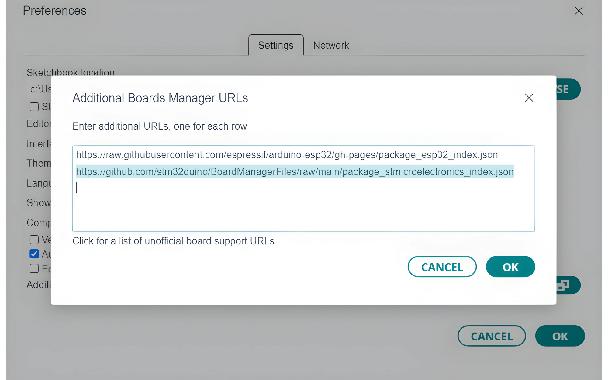
- Click
OK.
Step 4: Install STM32 Boards
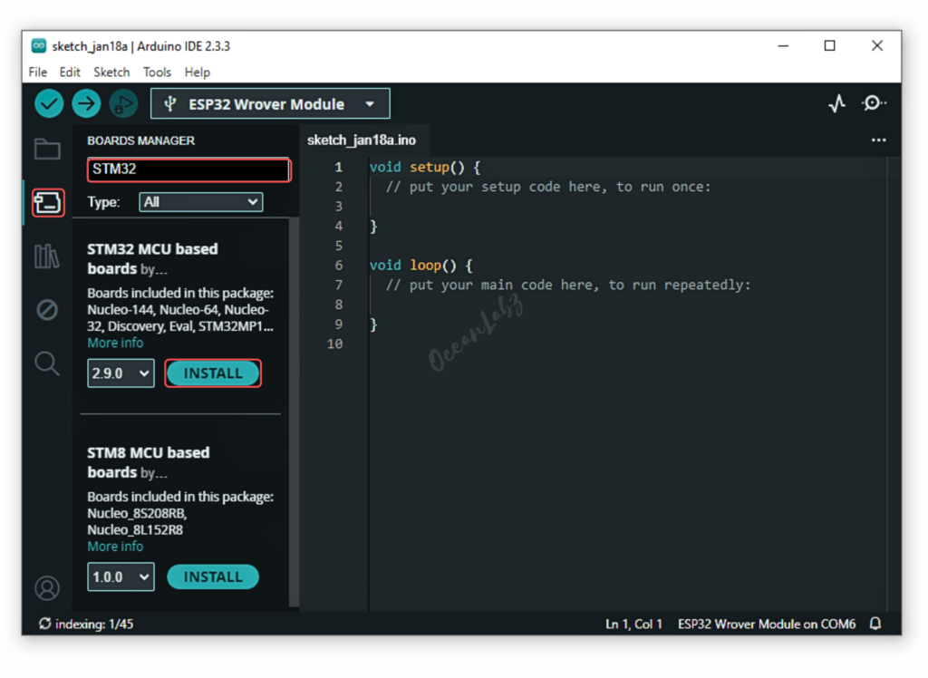
- Go to the “Board manager” tab on the left-hand side of the screen.
- Click on the “Board Manager” button (Board icon) at the top of the Board tab.
- In the Board Manager window, type “STM32” in the search bar.
- Locate the “STM32 MCU based board” Board click on the “Install” button next to it.
- Wait for the board to be installed.
Step 5: Connect the STM32F103C8T6 Board
Use a USB to UART adapter or ST-Link/V2 to connect your board:
- For USB to UART (Bootloader mode):
- Connect TX → RX, RX → TX, GND → GND, and 3.3V → VCC.
- Set the BOOT0 jumper to 1 (Programming Mode).
- For ST-Link: Connect the SWD pins (SWCLK, SWDIO, GND, 3.3V) to the ST-Link module.
Step 6: Select the STM32 Board
- Go to Tools > Board and select your STM32 board (e.g., “Generic STM32F1 series”).
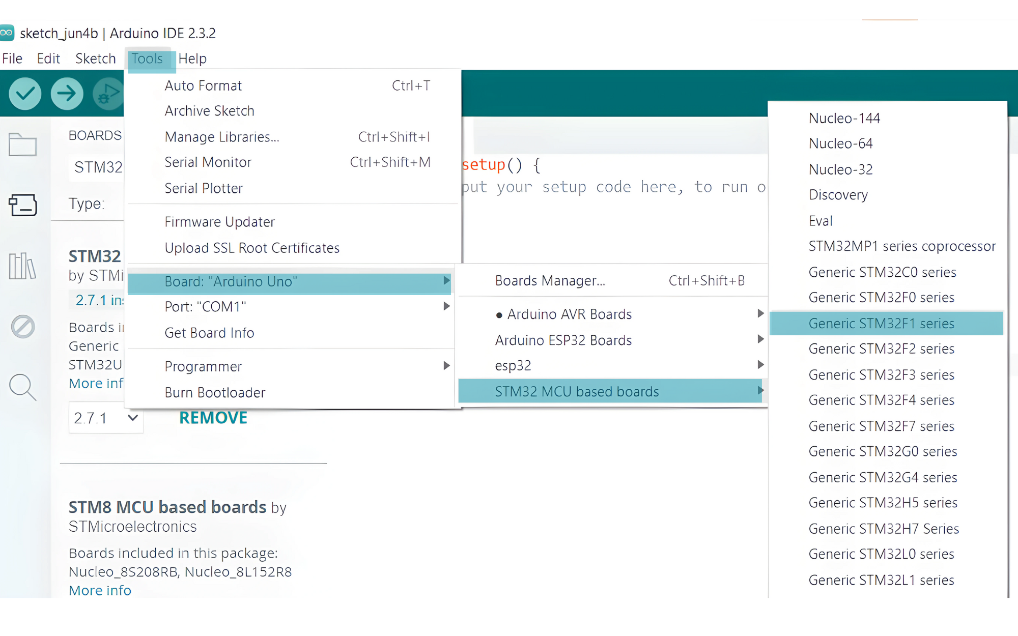
- Board Part Number: Select
STM32F103C8 (20k RAM, 64k Flash).Upload Method:
- Select
STM32CubeProgrammer (SWD)if using ST-Link. - Select
Serialif using USB to UART.
Port: Select the correct COM port for your adapter or ST-Link.
Sample Blink Code for STM32F103C8T6
void setup() {
  // Initialize the built-in LED pin as an output
  pinMode(PC13, OUTPUT);
}

void loop() {
  // Turn the LED on (HIGH is the voltage level)
  digitalWrite(PC13, HIGH);
  delay(1000); // Wait for a second

  // Turn the LED off by making the voltage LOW
  digitalWrite(PC13, LOW);
  delay(1000); // Wait for a second
}
By following these steps, you should be able to successfully program your STM32F103C8T6 microcontroller using the Arduino IDE
Troubleshooting Tips
- Error: No device found: Ensure the BOOT0 jumper is set correctly or check wiring.
- Upload fails with ST-Link: Verify that the SWD pins are securely connected.
- COM port not detected: Install USB-to-serial drivers properly.

