Index
Introduction:
The ESP32 is a powerful microcontroller with built-in Wi-Fi and Bluetooth capabilities. Here are some popular platforms for programming the ESP32:
- Arduino IDE:
- Description: An easy-to-use development environment popular among beginners and hobbyists. It provides a simple interface and a vast library ecosystem.
- PlatformIO:
- Description: An advanced, open-source development platform with support for multiple frameworks, libraries, and debugging tools. It integrates with various IDEs like Visual Studio Code and Atom.
- Espressif IoT Development Framework (ESP-IDF):
- Description: The official development framework provided by Espressif, offering extensive features and direct access to hardware capabilities. Suitable for more advanced users requiring fine-grained control over the ESP32.
- MicroPython:
- Description: A lightweight implementation of Python 3 optimized for microcontrollers. It enables rapid prototyping and ease of use, especially for those familiar with Python.
- Lua (NodeMCU):
- Description: A lightweight scripting language, allowing rapid development and deployment of IoT applications. NodeMCU firmware makes it easy to control ESP32 using Lua scripts.
Compared to other platforms, the Arduino IDE is the most user-friendly option for beginners. Although it may not be the best platform for utilizing all the features of the ESP32, its familiarity makes it an excellent starting point.
To use the Arduino IDE with the ESP32, you need to install the ESP32 board through the Arduino Board Manager. This guide will walk you through the steps to download, install, and test the ESP32 Arduino Core.
Step1: Install or Update the Arduino IDE:
Begin by ensuring that you have the latest version of the Arduino IDE installed on your computer. If not, it’s advisable to download and install it promptly.download
Step2: Install the USB-to-Serial Bridge Driver:
Since there are various ESP32-based development boards with different designs, you might need to install specific drivers for your USB-to-serial converter. These drivers are necessary to enable code uploading to your ESP32.
For example, some ESP32 boards use the CP2102 driver to convert USB signals to UART signals, while others use the CH340 driver. The ESP32-CAM, however, lacks an onboard USB-to-serial converter and requires a separate module.
If you haven’t previously installed drivers for these USB-to-serial converters on your computer, it’s essential to do so now.
Download CP210x USB to UART Drivers
Download CH340 Drivers
Step 3: Installing the ESP32 Arduino Core
- Launch the Arduino IDE.
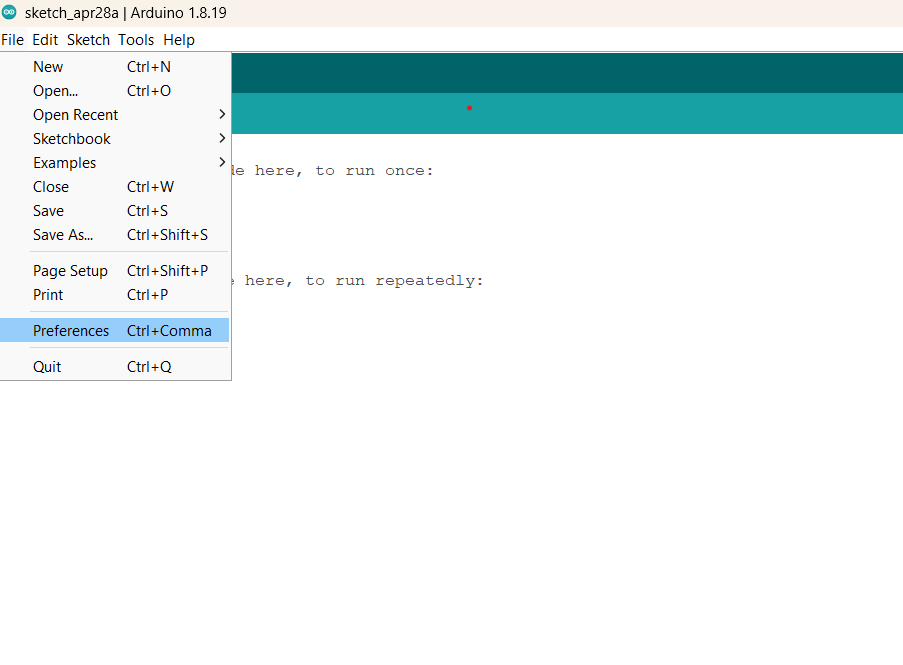
- Go to File > Preferences.
- In the “Additional Board Manager URLs” field, paste the following URL:
https://raw.githubusercontent.com/espressif/arduino-esp32/gh-pages/package_esp32_index.json- Click the “OK” button.
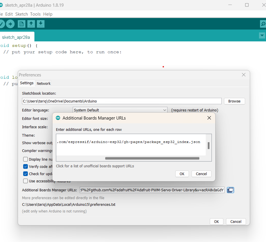
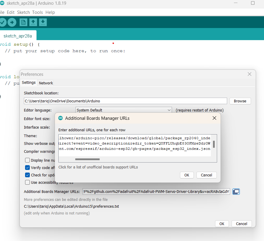
If you’ve previously added URLs for other boards, you can click the icon beside the field to open a window for adding additional URLs, one per row.
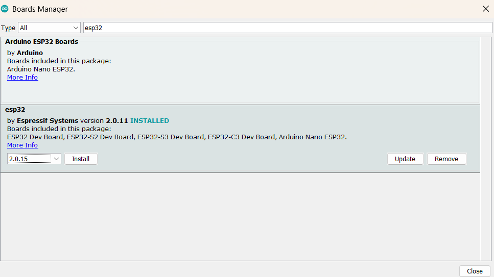
Go to Tools > Board > Boards Manager…

Refine your search by typing ‘esp32’. Locate ESP32 by Espressif Systems in the list. Click on it, then select Install.
Step 4: Select the Board and Port
Once you’ve installed the ESP32 Arduino Core, restart your Arduino IDE. Then, go to Tools > Board to verify that ESP32 boards are now available.
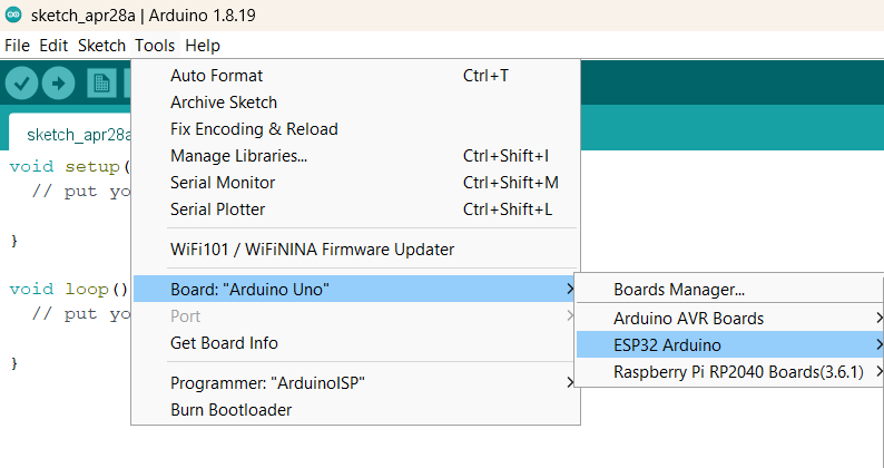
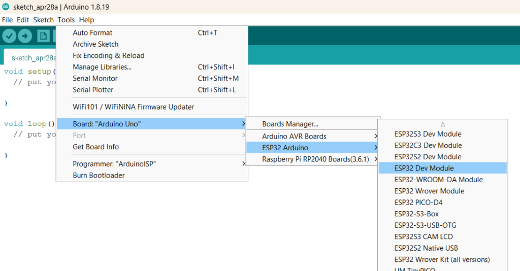
In the Tools > Board menu, choose your board. If you’re uncertain about your board, select ESP32 Dev Module.
Lastly, connect your ESP32 board to the computer and choose the appropriate port.
Note:
Always keep the ESP32 Arduino core up to date. Go to Tools > Board > Boards Manager, search for ESP32, and check your installed version. If there's a newer one, update it.
Step 5: Testing the Installation:
Now, you’re all set to test your ESP32 with a simple program. Open the Arduino IDE and connect your board.
Let’s upload a simple sketch – Blink!
// Define the digital pin connected to the LED
#define LED_PIN  2 // Change this to the desired digital pin number

void setup() {
  // Initialize the digital pin as an output
  pinMode(LED_PIN, OUTPUT);
}

void loop() {
  // Turn the LED on (HIGH) for 1 second
  digitalWrite(LED_PIN, HIGH);
  delay(1000);
  // Turn the LED off (LOW) for 1 second
  digitalWrite(LED_PIN, LOW);
  delay(1000);
}
If everything worked, the on-board LED on your ESP32 should start blinking.


Comments (2)