Index

Introduction
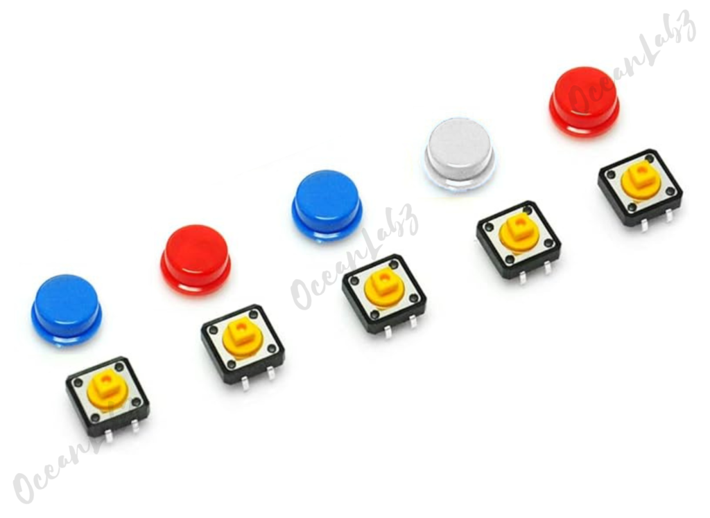
The standalone Tactile Push Button is a simple mechanical switch that completes a circuit when pressed, allowing current to flow. It doesn’t include any built-in components like resistors, so external resistors are often needed for stability. In this tutorial, we will learn how to connect and use this basic push button with an Arduino to detect its on/off state.
Required Components
- Arduino UNO or Nano
- Standalone Tactile Push Button
- 10kΩ resistor
- Jumper wires
- Breadboard
- LED (optional)
Pinout
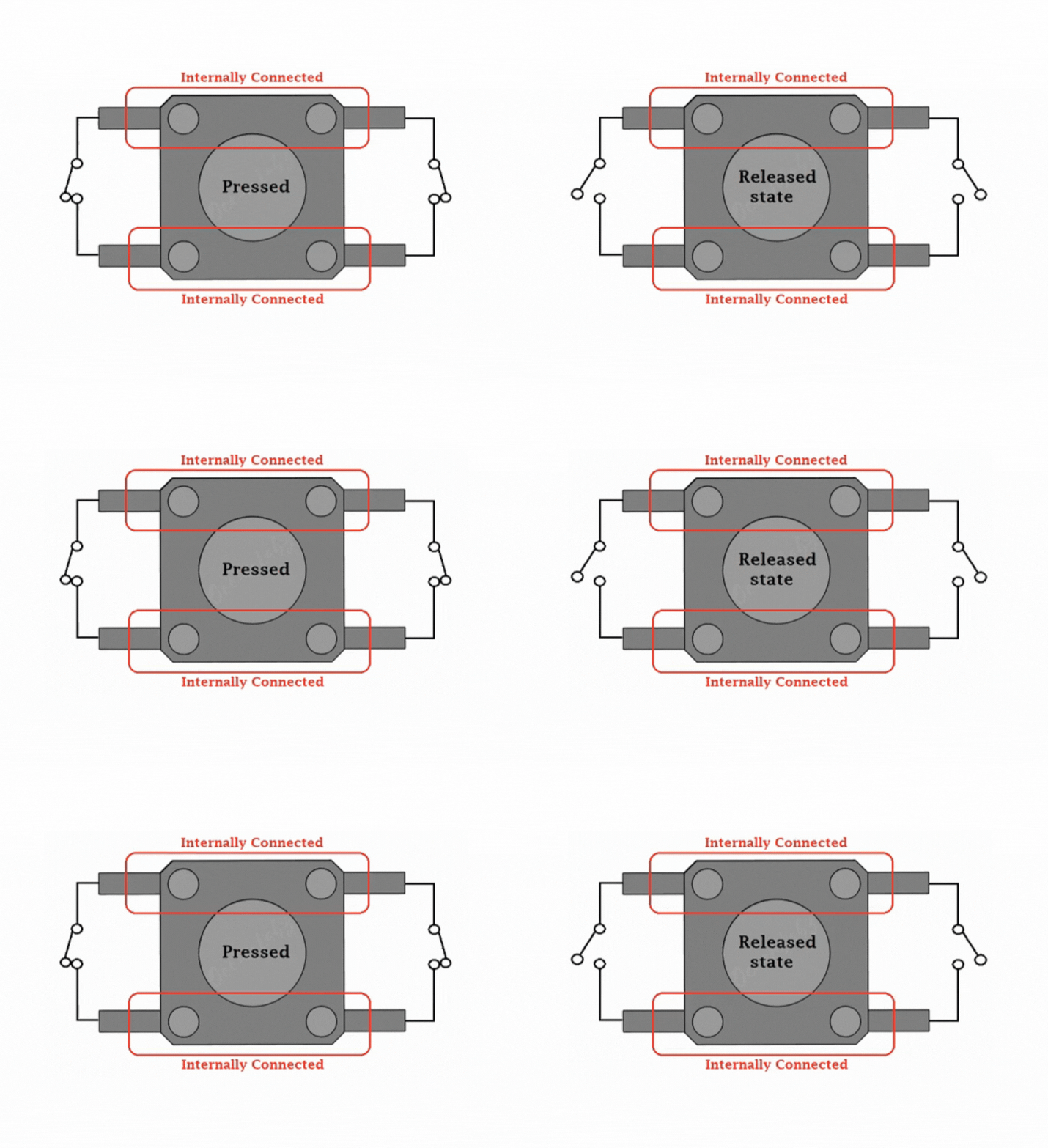
- Button Pressed: When you press the button, the metal contacts inside touch, creating a connection. This allows electricity to flow, completing the circuit.
- Button Released: When you release the button, the contacts separate, breaking the connection. This stops the flow of electricity, turning off whatever device it’s controlling.

Circuit Diagram / Wiring
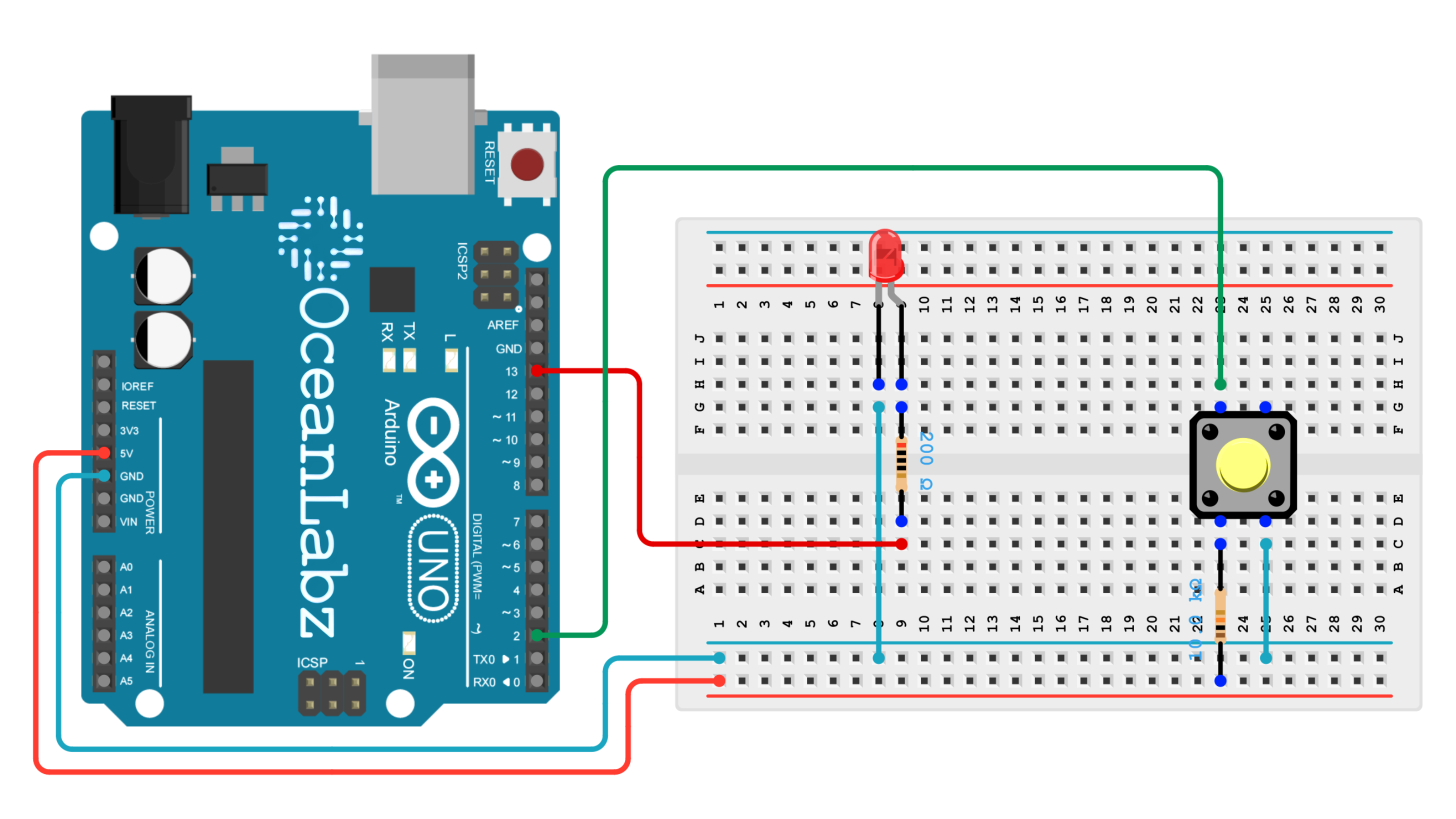
- LED longer leg (anode) through a 220-ohm resistor → D13 (Arduino)
- LED shorter leg (cathode) → GND (Arduino)
- Push Button Connect the other leg with 10k-ohm resistor to 5V (pull-up) → Pin D2 (Arduino)

Arduino Code / Programming
Upload the following code to your Arduino to read the button’s state:
#define BUTTON_PIN 2
#define LED_PIN 13

bool ledState = false;  // Current LED state
bool lastButtonState = HIGH;  // Stores the previous button state

void setup() {
  pinMode(BUTTON_PIN, INPUT_PULLUP);  // Enable internal pull-up resistor
  pinMode(LED_PIN, OUTPUT);
  Serial.begin(9600);
}

void loop() {
  // Read the current button state
  bool currentButtonState = digitalRead(BUTTON_PIN);

  // Check if the button state has changed from HIGH to LOW (button press)
  if (currentButtonState == LOW && lastButtonState == HIGH) {
    ledState = !ledState;  // Toggle LED state
    digitalWrite(LED_PIN, ledState);  // Set LED
    Serial.println(ledState ? "LED ON" : "LED OFF");
    delay(50);  // Debounce delay
  }

  // Update the last button state
  lastButtonState = currentButtonState;
}
Explanation of the Code
- Setup: Configures the button pin with a pull-up resistor and the LED pin as output.
- Loop:Reads the button state.
- Toggles the LED state (ON/OFF) on each button press.
- Includes a debounce delay to ensure stable readings.
Testing and Troubleshooting
- Make sure the button and resistor are properly connected.
- If the button is not detected, try a different pin.


