Index
Introduction
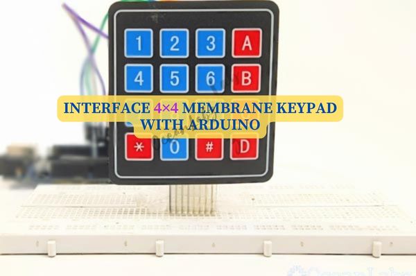
A 4×4 membrane keypad is an input device that enables users to enter alphanumeric characters or control a system by pressing a series of buttons. Keypads are used in many applications, such as security systems, access control, vending machines, and industrial control systems. Among various types of keypads, 4×4 and 4×3 membrane keypads are popular choices for hobbyists and electronics enthusiasts due to their low cost, ease of use, and versatility. In this article, we will explore the basics of 4×4 and 4×3 membrane keypads and how to interface them with an Arduino.
Working Principal
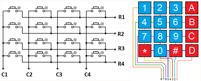
Matrix keypad consists of set of Push buttons, which are interconnected. Like in our case we are using 4X4 matrix keypad, in which there are 4 push buttons in each of four rows. And the terminals of the push buttons are connected according to diagram. In first row, one terminal of all the 4 push buttons are connected together and another terminal of 4 push buttons are representing each of 4 columns, same goes for each row.
- First we have made all the Rows to Logic level 0 and all the columns to Logic level 1.
- Whenever we press a button, column and row corresponding to that button gets shorted and makes the corresponding column to logic level 0. Because that column becomes connected (shorted) to the row, which is at Logic level 0. So we get the column no. See main() function.
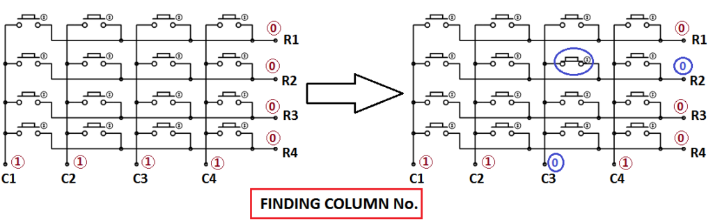
3. Now we need to find the Row no., so we have created four functions corresponding to each column. Like if any button of column one is pressed, we call function row_finder1(), to find the row no.
4. In row_finder1() function, we reversed the logic levels, means now all the Rows are 1 and columns are 0. Now Row of the pressed button should be 0 because it has become connected (shorted) to the column whose button is pressed, and all the columns are at 0 logic. So we have scanned all rows for 0.
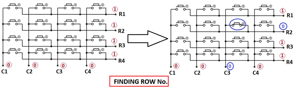
5. So whenever we find the Row at logic 0, means that is the row of pressed button. So now we have column no (got in step 2) and row no., and we can print no. of that button using lcd_data function.
Application
- Password-Based Security Systems:
- Digital Door Locks:
- Home Automation Systems:
Technical Specifications
- 16 keys in a compact 4×4 grid.
- Membrane switches with tactile feedback.
- Requires 100-200g force per key.
- Low contact resistance.
- Operates at 3-24V DC.
- Works in -20°C to +70°C.
- Long lifespan, millions of presses.
- Interfaces with microcontrollers.
- Mounts easily with adhesive or holes.
- Resistant to dust, moisture, and chemicals.
Pinout
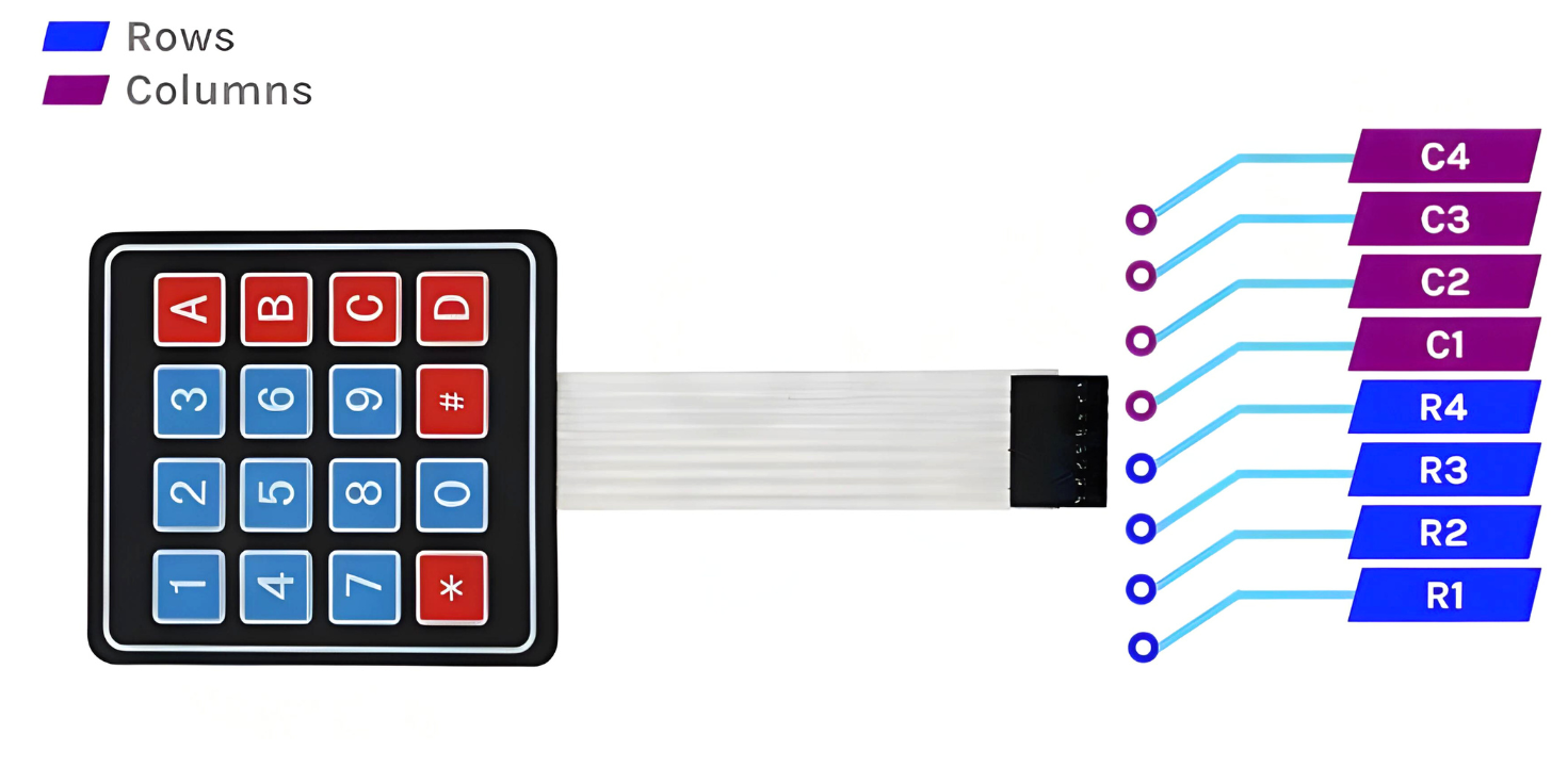
- Row pins (4 pins): Connected to digital pins of the Arduino (e.g., pins 6, 7, 8, 9)
- Column pins (4 pins): Connected to digital pins of the Arduino (e.g., pins 2, 3, 4, 5)
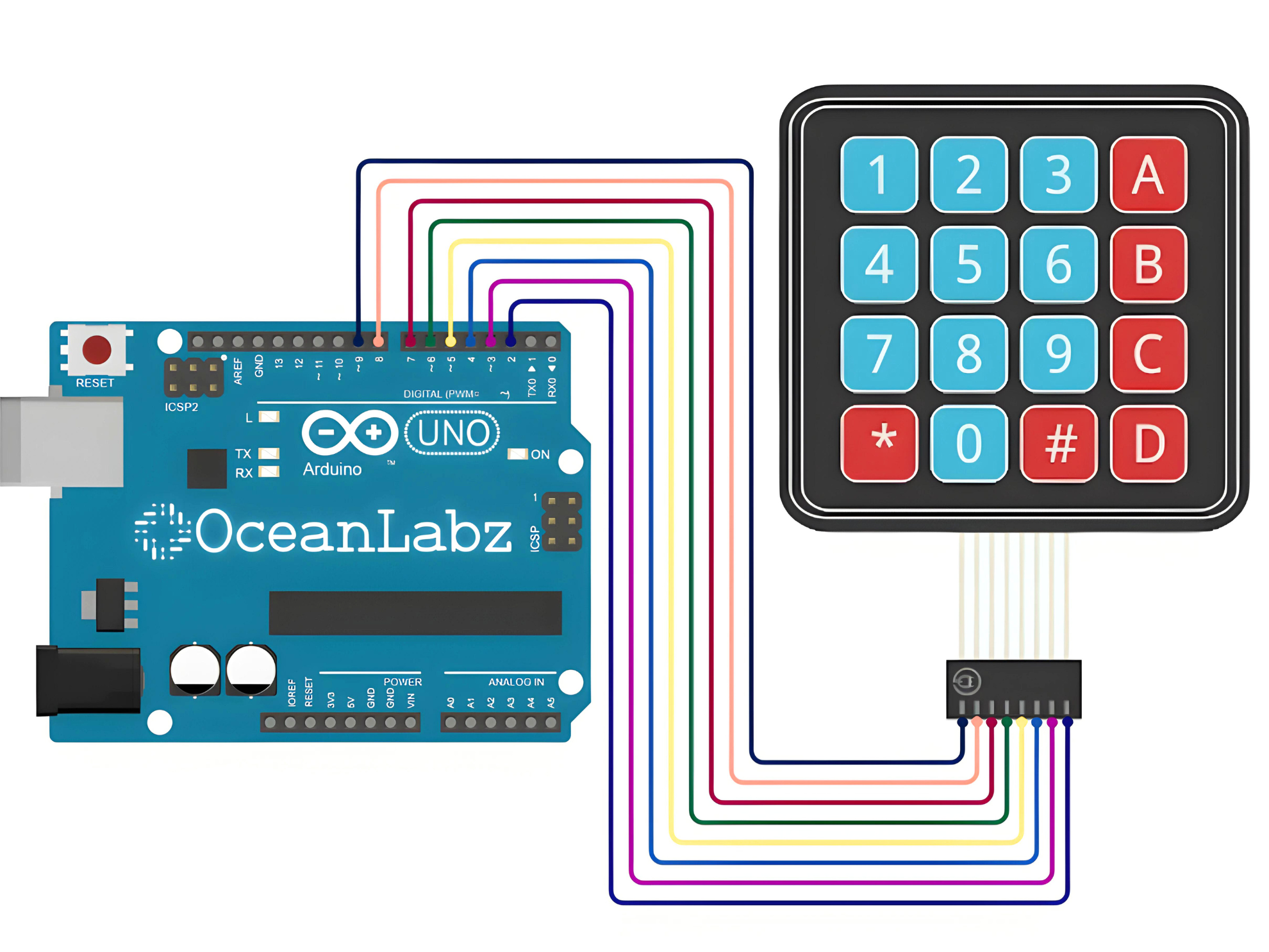
Circuit Diagram
| Keypad Pin | Arduino Pin |
| Column 4 | D2 |
| Column 3 | D3 |
| Column 2 | D4 |
| Column 1 | D5 |
| Row 4 | D6 |
| Row 3 | D7 |
| Row 2 | D8 |
| Row 1 | D9 |
Programming With Arduino
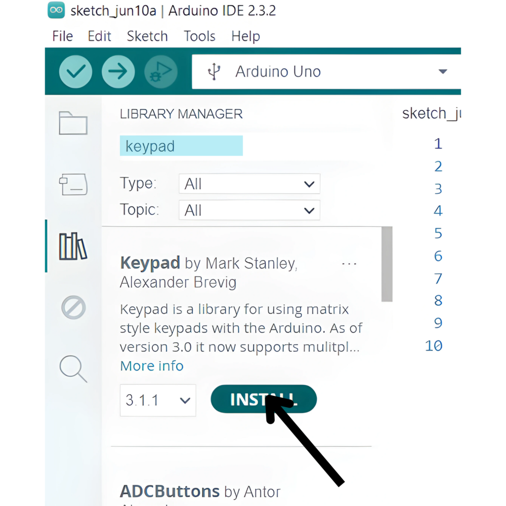
Step 1: Install the Keypad Library
Before uploading the code to your Arduino, ensure you have the Keypad library installed. You can install it via the Arduino Library Manager:
- Open the Arduino IDE.
- Go to Sketch > Tools > Manage Libraries.
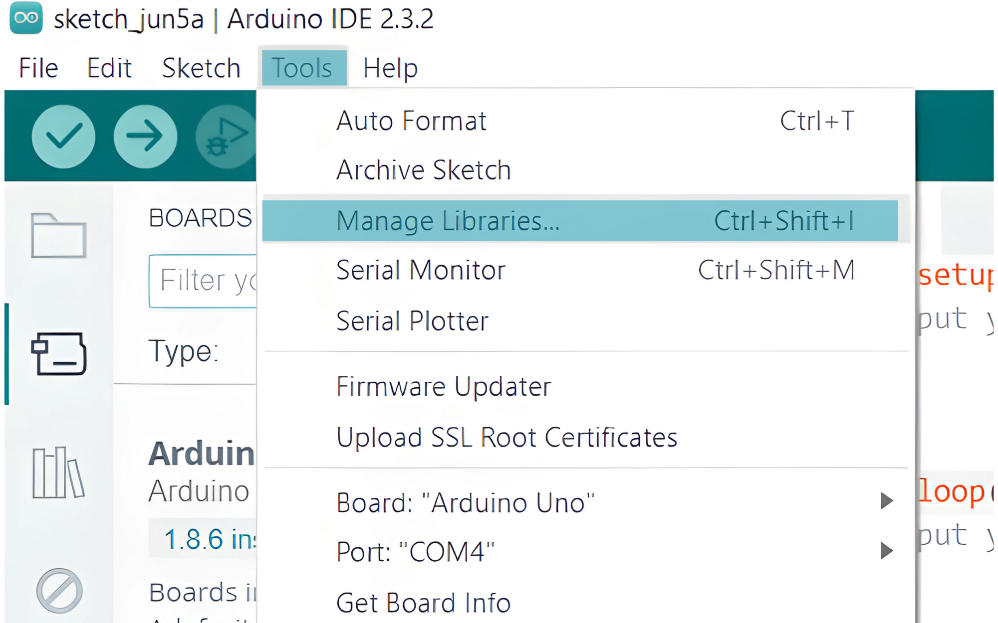
- Search for Keypad by Mark Stanley and Alexander Brevig.
- Install the library.
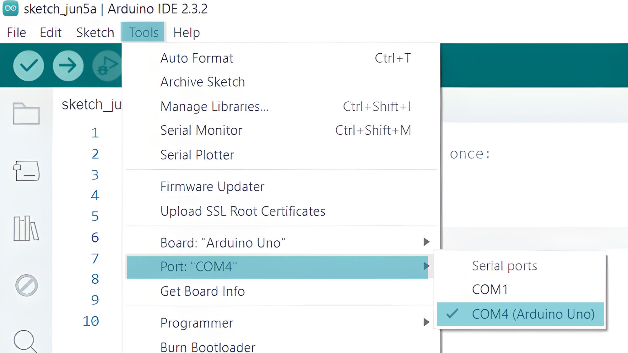
Step 2: Select the appropriate board and port
- Go to Tools > Board and select your Arduino board (e.g., Arduino Uno).
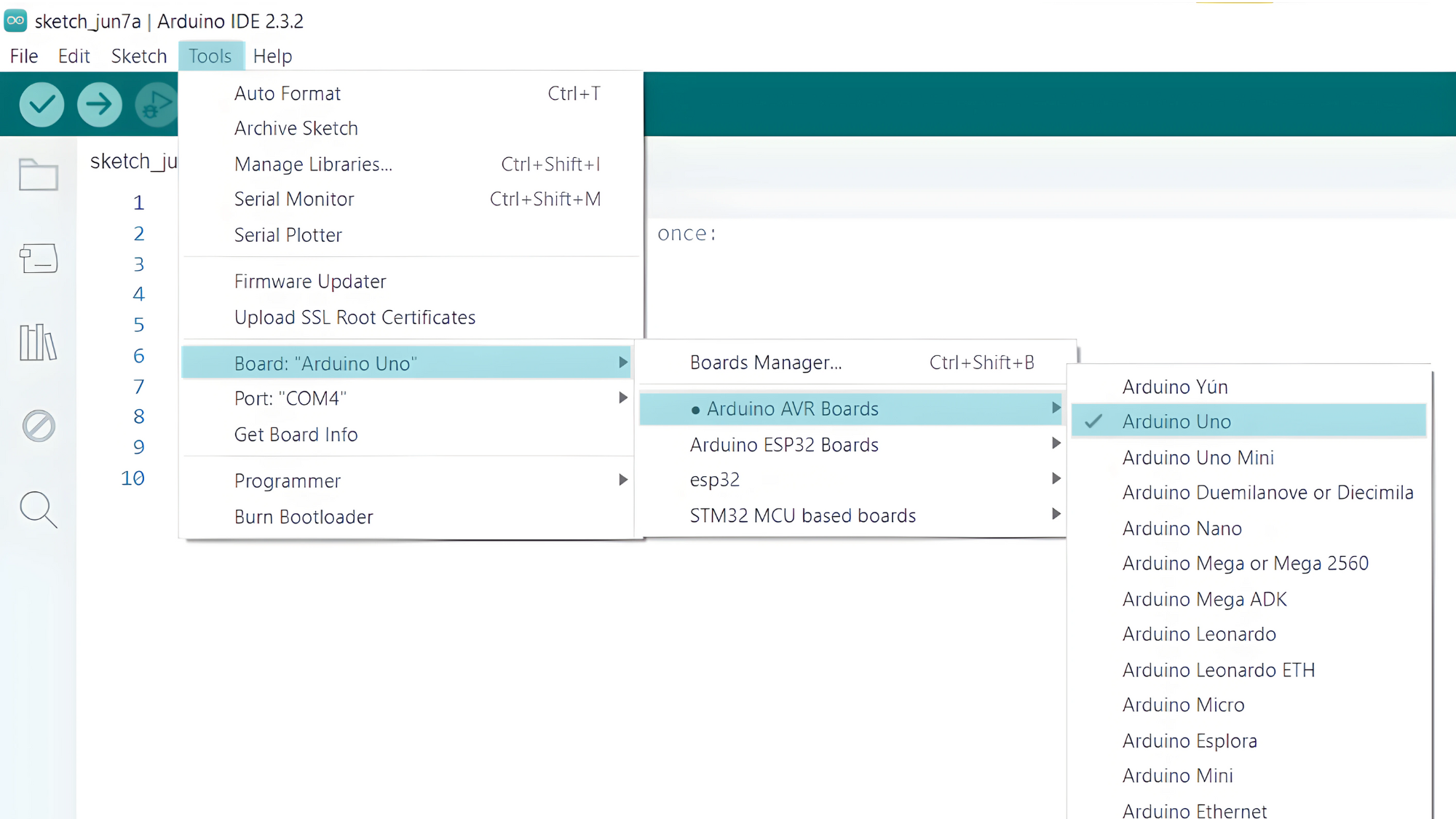
- Go to Tools > Port and select the port to which your Arduino is connected.
Step 3: Upload the Code
- Copy the provided code into your Arduino IDE.
#include <Keypad.h>
const byte numRows = 4; // Number of rows
const byte numCols = 4; // Number of columns
char keys[numRows][numCols] = {
  {'1','2','3','A'},
  {'4','5','6','B'},
  {'7','8','9','C'},
  {'*','0','#','D'}
};
byte rowPins[numRows] = {9, 8, 7, 6}; // Row pin numbers
byte colPins[numCols] = {5, 4, 3, 2}; // Column pin numbers
Keypad keypad = Keypad(makeKeymap(keys), rowPins, colPins, numRows, numCols);
void setup() {
  Serial.begin(9600);
}
void loop() {
  char key = keypad.getKey();
  if (key != NO_KEY) {
    Serial.println(key);
    delay(200); // Debounce delay
  }
}
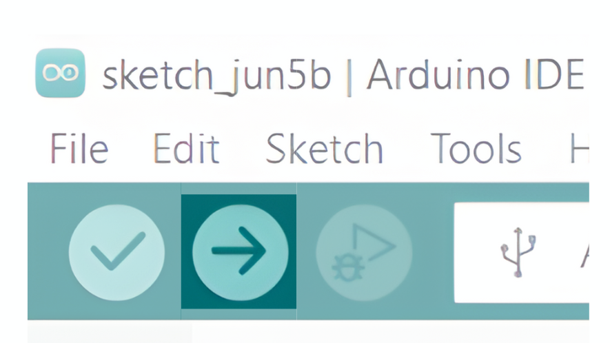
- Verify and upload the code to your Arduino board.
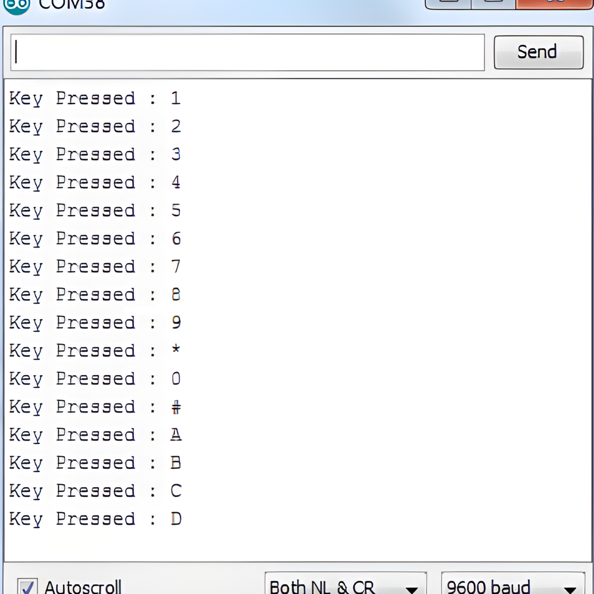
Step 4: Open the Serial Monitor
- Connect your Arduino to the computer and upload the code.
- Open the Serial Monitor in the Arduino IDE by going to Tools > Serial Monitor or pressing
Ctrl+Shift+M. - Set the baud rate to 9600 in the Serial Monitor.