Index
Introduction
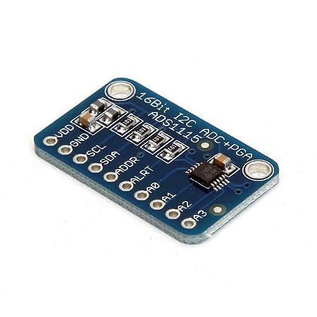
The ADS1115 is a 16-bit Analog-to-Digital Converter (ADC) featuring four input channels and a programmable gain amplifier. It converts analog signals into digital data with high precision, making it ideal for applications requiring accurate sensor measurements. The ADS1115 communicates over the I2C protocol, simplifying integration with microcontrollers. It includes configurable features such as programmable gain settings and adjustable data rates, offering flexibility for various sensor interfacing tasks. This ADC is commonly used in sensor interfaces, data acquisition systems, IoT devices, and other applications demanding reliable and precise analog-to-digital conversion.
Working Principle
- Analog Input: The ADS1115 has four input channels that can connect to external analog sensors or voltage sources. Each channel can measure voltages in the range of 0 to the supply voltage (typically 3.3V or 5V).
- Programmable Gain Amplifier (PGA): The ADC includes a programmable gain amplifier that allows you to adjust the gain to amplify small voltage signals. This feature enhances the sensitivity and resolution of the ADC.
- Analog-to-Digital Conversion: When initiated by a microcontroller over the I2C interface, the ADS1115 performs analog-to-digital conversion on the input voltage signals. It uses a 16-bit sigma-delta ADC to achieve high-resolution conversion.
- Internal Reference Voltage: The ADC includes an internal voltage reference that determines the maximum voltage range for conversion. This reference can be set to the supply voltage or a known voltage level for accurate measurements.
- I2C Communication: The ADS1115 communicates with a microcontroller or host device using the I2C protocol. Through I2C commands, the microcontroller can configure the ADC settings, start conversions, and read the digital conversion results.
- Data Rate Control: The ADS1115 allows you to set the data rate (sampling rate) for the ADC conversions based on the desired application requirements. The data rate can range from 8 to 860 samples per second (SPS).
- Output Digital Values: After converting the analog voltage into digital values, the ADS1115 outputs the 16-bit digital result over the I2C interface. The microcontroller can then process these digital values for further analysis or use in the application.
Applications
- Sensor interfaces for temperature, pressure, strain gauges, and other analog sensors
- Data acquisition systems for industrial monitoring and scientific instrumentation
- IoT devices requiring accurate sensor data acquisition
- Audio signal processing and digital audio applications
- Medical devices such as ECG monitors and blood pressure monitors
- Automated test equipment for precise voltage measurements
Technical Specifications
- Operating Voltage\: 2.0V to 5.5V
- PROGRAMMABLE DATA RATE: 8SPS to 860SPS
- Internal low-drift voltage reference
- Programmable comparator
- This board/chip uses I2C 7-bit addresses between 0x48-0x4B, selectable with jumpers
Pinout
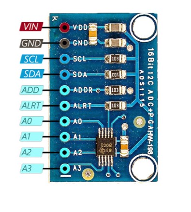
- VDD: Connect this pin to the positive supply voltage (typically 3.3V or 5V).
- GND: Connect this pin to the ground (0V) of the power supply.
- SCL: Serial Clock input for I2C communication with the microcontroller.
- SDA: Serial Data input/output for I2C communication with the microcontroller.
- ADDR: Address pin for setting the I2C address of the ADS1115 (can be connected to VDD, GND, SDA, or SCL to set the address).
Circuit Diagram
| ADS1115 Pin | Arduino Pin |
| VCC | 5 V |
| GND | GND |
| SDA | Analog A4 |
| SCL | Analog A5 |

Programming With Arduino
Step 1: Open your first sketch
- Open the Arduino IDE.
- Copy and paste the provided code into a new sketch in the Arduino IDE:
#include <Wire.h>
#include <Adafruit_ADS1015.h>

Adafruit_ADS1115 ads;  // Create an ADS1115 instance

void setup() {
  Serial.begin(9600);  // Initialize serial communication

  // Initialize ADS1115 at the default address (ADDR connected to GND)
  if (!ads.begin()) {
    Serial.println("Failed to initialize ADS1115!");
    while (1);
  }

  // Set the gain (optional, default is +/-6.144V)
  ads.setGain(GAIN_TWOTHIRDS);  // Set gain to +/-6.144V range
}

void loop() {
  // Read analog voltage from channel 0 (A0) in single-ended mode
  int16_t adc0 = ads.readADC_SingleEnded(0);

  // Convert ADC value to voltage (assuming +/-6.144V range and 16-bit resolution)
  float voltage0 = adc0 * 0.1875;  // 0.1875mV per LSB for +/-6.144V range

  // Print the voltage value to the Serial Monitor
  Serial.print("Voltage on A0: ");
  Serial.print(voltage0);
  Serial.println(" mV");

  delay(1000);  // Delay for readability
}
Step 2: Install the Required Library
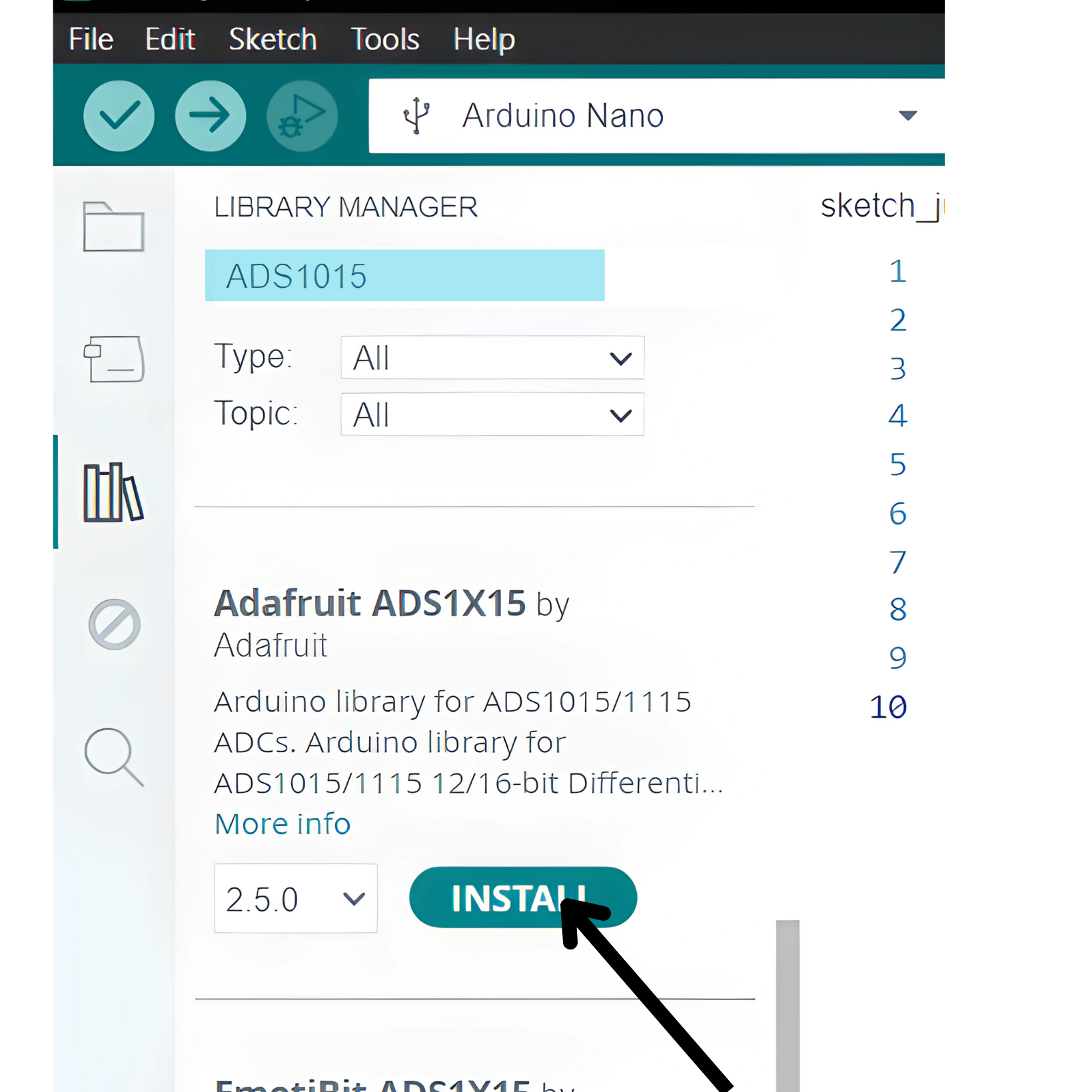
- Go to Sketch > Tools> Manage Libraries.
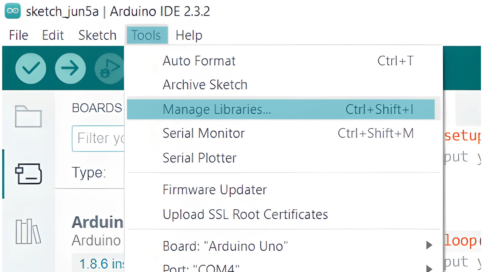
- Search for “ADS1115” and install the Adafruit ADS1X15 library by Adafruit.
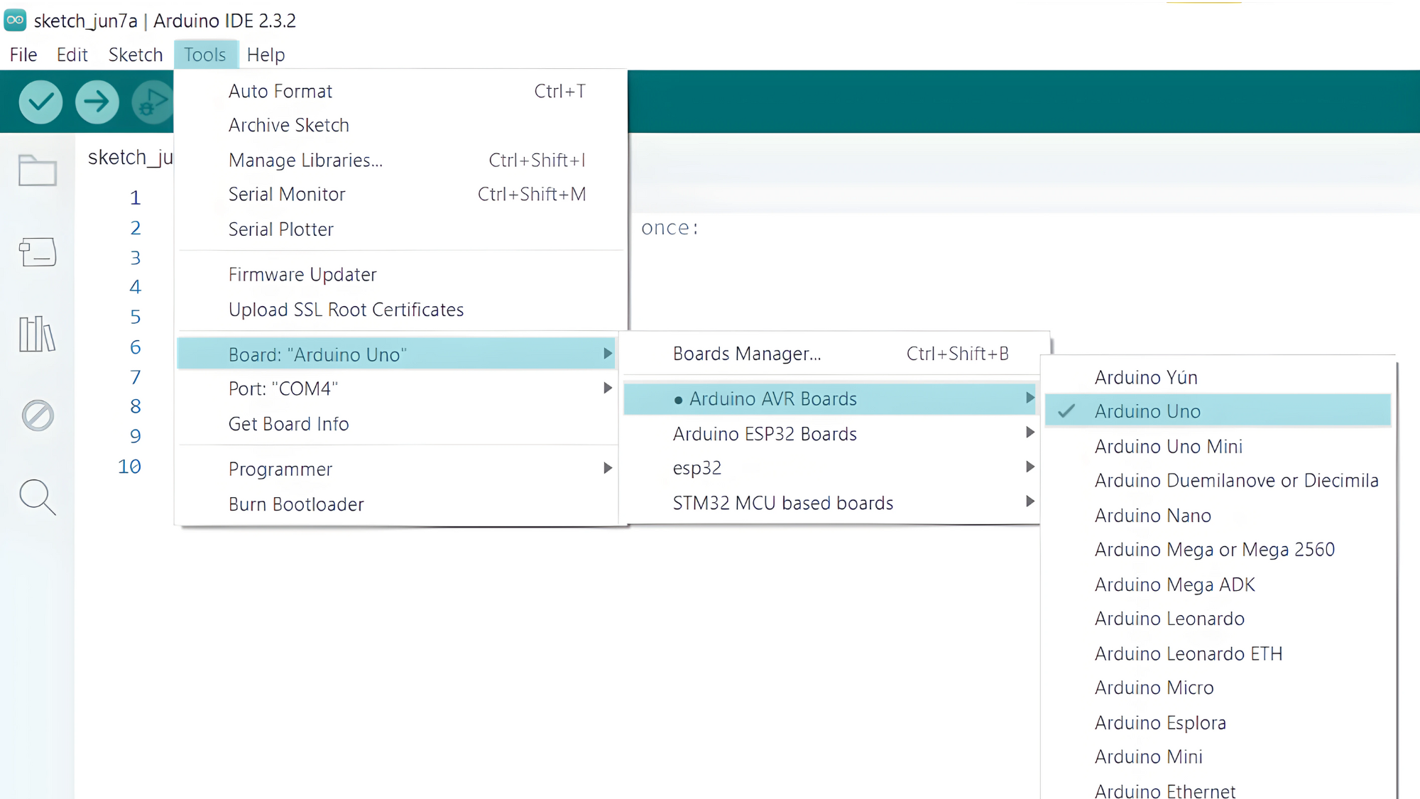
Step 3: Select your board type and port
- In the Arduino IDE, select your Arduino board from
Tools>Board.
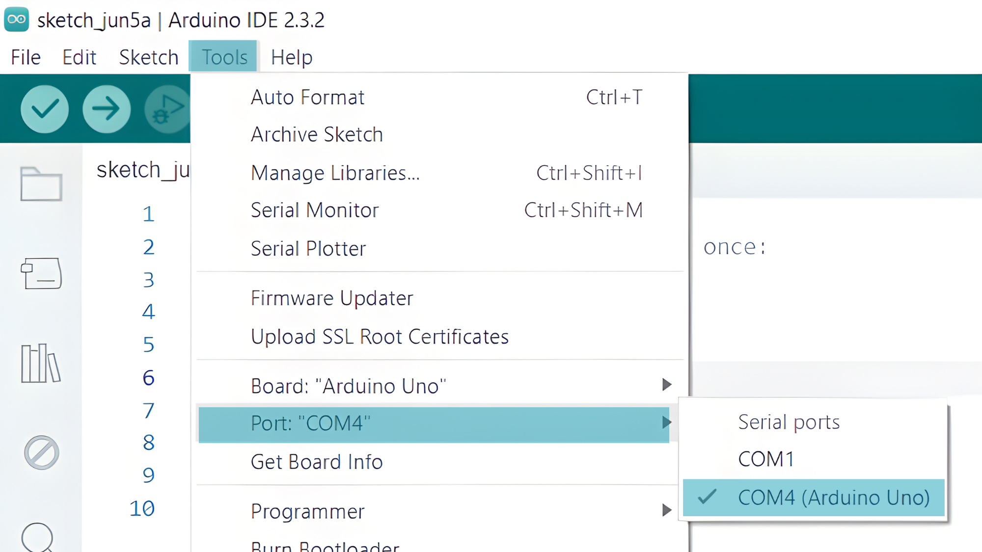
- Go to Tools > Port and select the port to which your Arduino is connected.
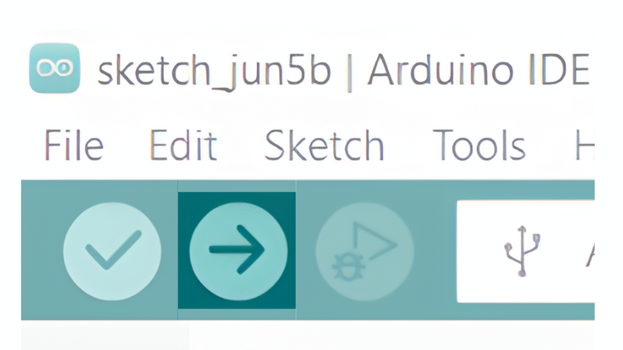
Step 4: Upload the Sketch
- Click the “Upload” button (right arrow icon) to upload the sketch to the Arduino.
Step 5: Open Serial Monitor
- After uploading the code, open the Serial Monitor from the Tools menu or press Ctrl+Shift+M.
- Set the baud rate to 9600.

