Index
Introduction
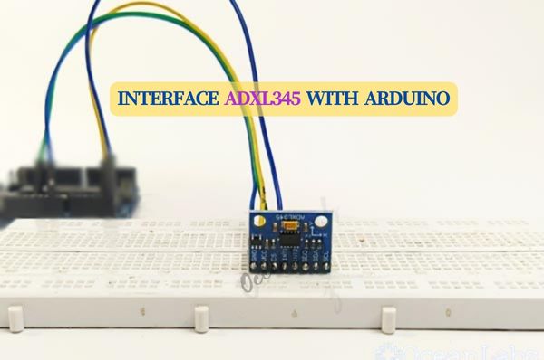
The ADXL345 is a small, thin, low-power, 3-axis accelerometer module developed by Analog Devices. It is widely used in various applications such as motion sensing, tilt sensing, and vibration monitoring. The ADXL345 measures acceleration with high resolution (up to 13-bit), providing data in digital form via SPI (Serial Peripheral Interface) or I2C (Inter-Integrated Circuit) communication protocols. It’s commonly utilized in consumer electronics, robotics, wearable devices, and motion-sensitive applications.
Working Principle
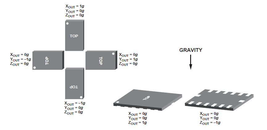
It can be noted that axes of acceleration are indicated on the module. Otherwise, the axes of accelerations can be found with respect to the top view of the sensor, as shown below:
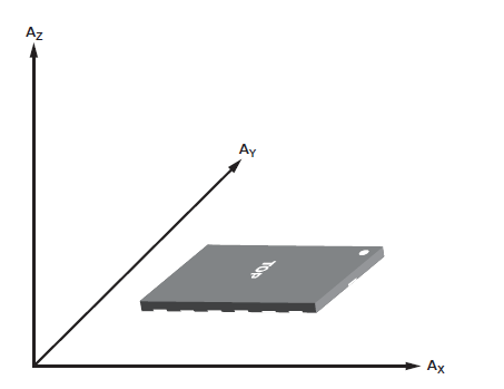
The ADXL345 sensor is sensitive to both static acceleration (acceleration due to gravity) as well as dynamic acceleration (acceleration resulting from motion or shock). The sensor has the output response, as shown in the image below, with respect to its orientation to gravity.
Applications
- Motion Sensing: Detects movement, tilt, and acceleration in devices like smartphones and game controllers.
- Activity Tracking: Monitors physical activity in fitness trackers and wearable devices.
- Gesture Recognition: Interprets specific gestures for user interface controls.
- Vibration Analysis: Detects and analyzes vibrations in machinery and structures.
- Impact Detection: Identifies impacts or collisions in sports equipment and safety devices.
- Robotics: Provides motion feedback and stabilization in robotic systems.
- IoT Integration: Enables motion-based triggers and data collection in IoT devices.
Technical Specifications
- Sensor: ADXL345
- Axes: Triple axis (X, Y, Z)
- Interface: I2C or SPI
- Resolution: 10-bit or 13-bit
- Range: ±2g, ±4g, ±8g, or ±16g
- Features: High-resolution measurement, low power consumption, digital output
- Applications: Robotics, motion tracking, tilt sensing
- Compatibility: Various microcontrollers
Pinout
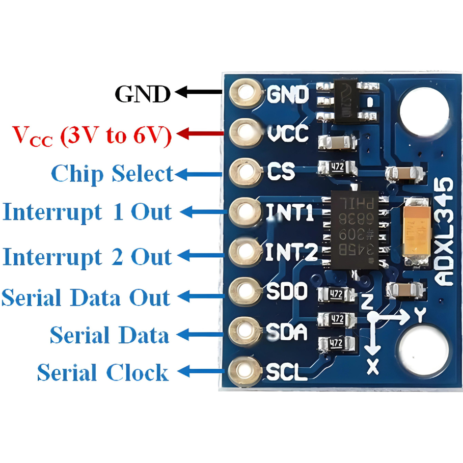
- VCC: Connect to 3.3V or 6V for power.
- GND: Ground connection.
- CS: Chip Select (can be connected to an MCU GPIO pin for SPI communication).
- SDO/ALT ADDRESS: Output Data, also used for alternate I2C address selection.
- SDA: Serial Data Line (I2C).
- SCL: Serial Clock Line (I2C).
- INT1: Interrupt 1 (can be configured for various accelerometer events).
- INT2: Interrupt 2 (similar to INT1).
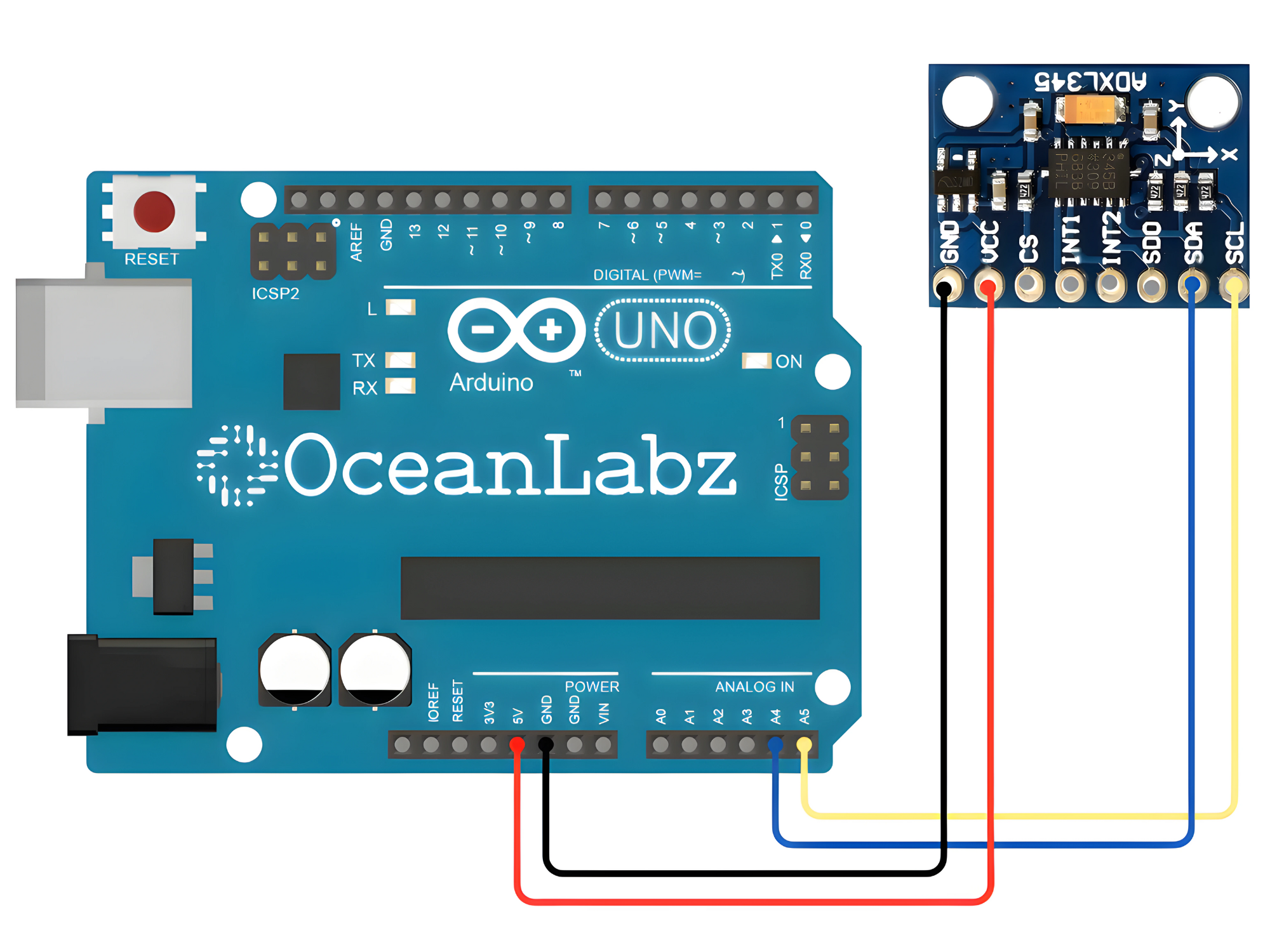
Circuit Diagram
| ADXL345 Pin | Arduino Pin |
| VCC | 5V |
| GND | GND |
| SDA | Analog 4 |
| SCL | Analog 5 |
Programming With Arduino
Step 1: Open your first sketch
- Open the Arduino IDE.
- Copy and paste the provided code into a new sketch in the Arduino IDE:
- The Wire library is included by default with the Arduino IDE, so you do not need to install it separately.
#include <Wire.h>

#define ADXL345_ADDRESS (0x53) // ADXL345 I2C address

void setup() {
  Serial.begin(9600);
  Wire.begin(); // Initialize I2C communication

  // Configure ADXL345
  writeToADXL345(0x2D, 0x08); // Power on and enable measurement
}

void loop() {
  // Read accelerometer data
  int x = readFromADXL345(0x32); // X-axis data (8 bits)
  int y = readFromADXL345(0x34); // Y-axis data (8 bits)
  int z = readFromADXL345(0x36); // Z-axis data (8 bits)

  // Print accelerometer data
  Serial.print("X = ");
  Serial.print(x);
  Serial.print(", Y = ");
  Serial.print(y);
  Serial.print(", Z = ");
  Serial.println(z);

  delay(100); // Delay between readings
}

// Function to write to ADXL345 register
void writeToADXL345(byte regAddress, byte value) {
  Wire.beginTransmission(ADXL345_ADDRESS);
  Wire.write(regAddress);
  Wire.write(value);
  Wire.endTransmission();
}

// Function to read from ADXL345 register
int readFromADXL345(byte regAddress) {
  Wire.beginTransmission(ADXL345_ADDRESS);
  Wire.write(regAddress);
  Wire.endTransmission(false); // Restart transmission for reading
  Wire.requestFrom(ADXL345_ADDRESS, 1); // Request 1 byte of data
  if (Wire.available()) {
    return Wire.read();
  }
  return -1; // Return error if no data received
}
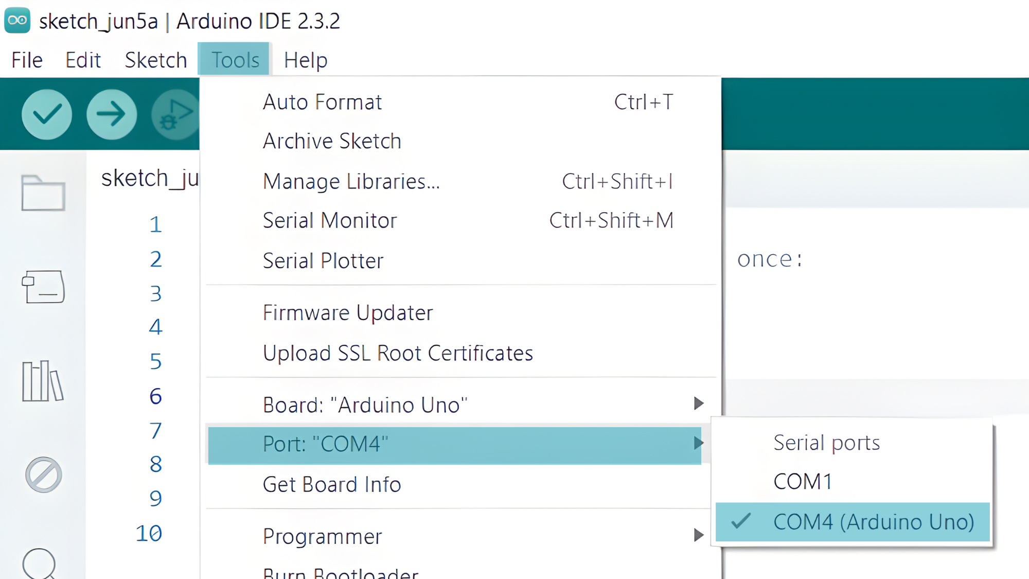
Step 2: Select the appropriate board and port
- Go to Tools > Board and select your Arduino board (e.g., Arduino Uno).
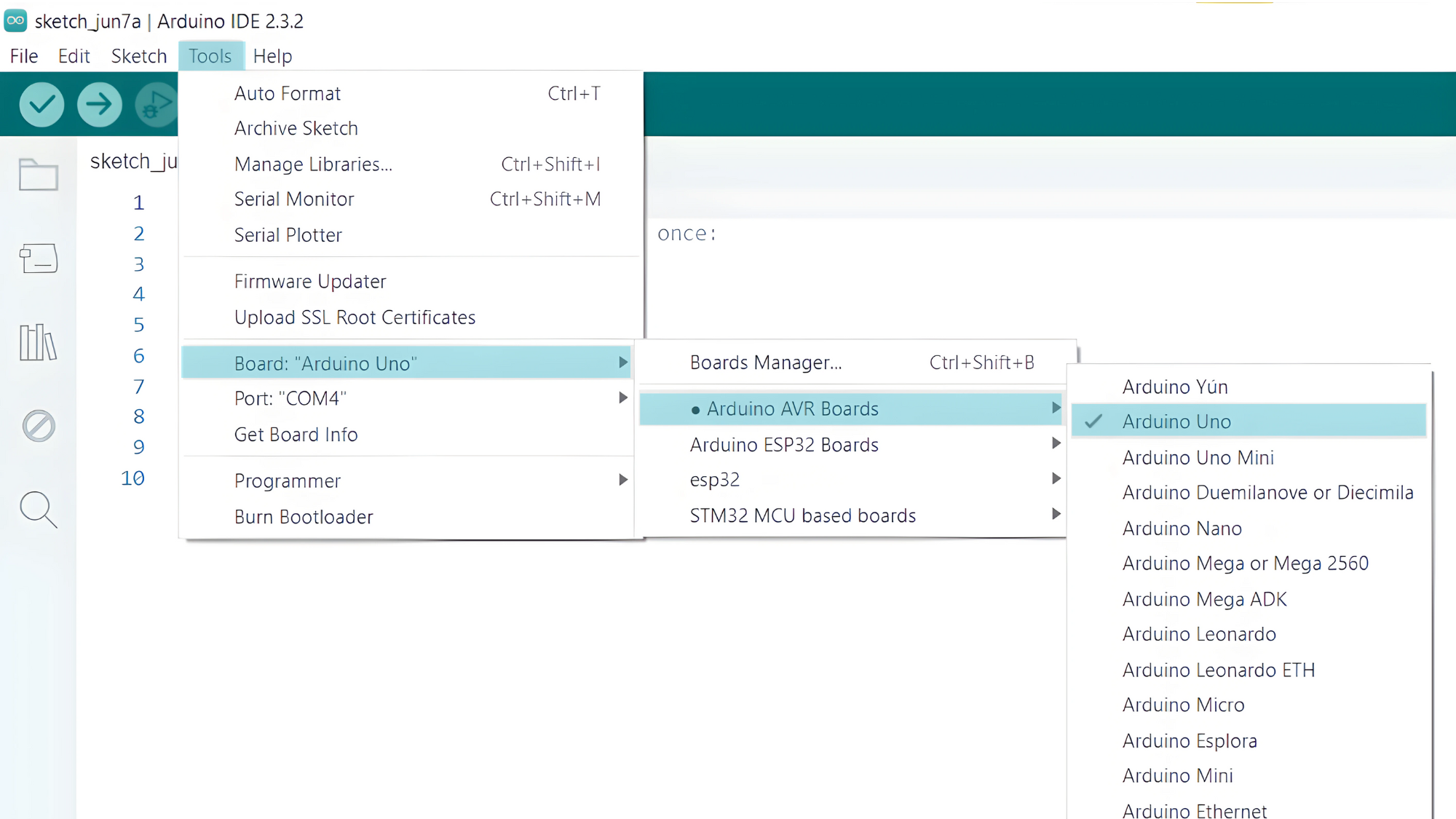
- Go to Tools > Port and select the port to which your Arduino is connected.
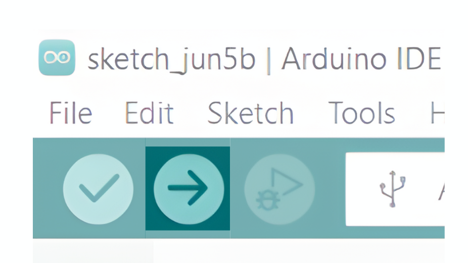
Step 3: Upload the Code
- Verify and upload the code to your Arduino board.
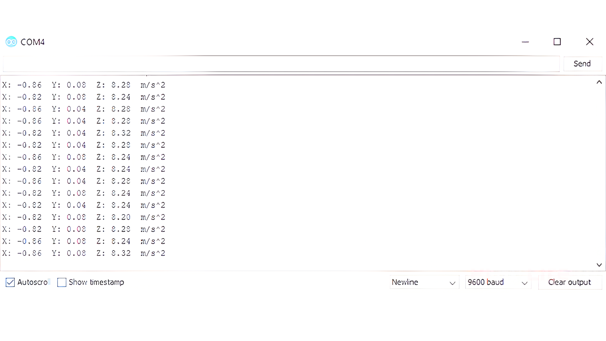
Step 4: Open the Serial Monitor
- Connect your Arduino to the computer and upload the code.
- Open the Serial Monitor in the Arduino IDE by going to Tools > Serial Monitor or pressing
Ctrl+Shift+M. - Set the baud rate to 9600 in the Serial Monitor.