Index
Introduction
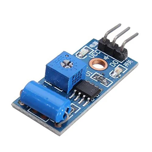
The SW420 vibration sensor is a module that detects vibrations and outputs a digital signal when it detects a certain threshold of vibration. It consists of a sensitive component (a spring-based tilt sensor) and a comparator circuit for digital output. When vibrations exceed the set threshold, the sensor outputs a HIGH signal; otherwise, it remains LOW. This sensor is commonly used in various applications such as motion detection, alarm systems, and vibration-sensitive devices. Its simplicity and ease of use make it popular for hobbyist and prototyping projects.
Hardware Overview
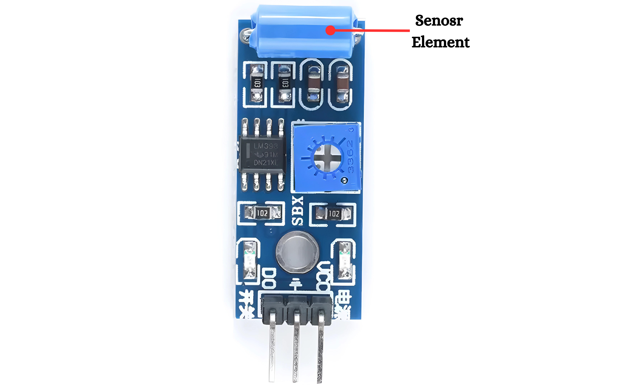
Sensor Element
- SW-420: This is a simple vibration sensor switch that closes the circuit when vibrations are detected.
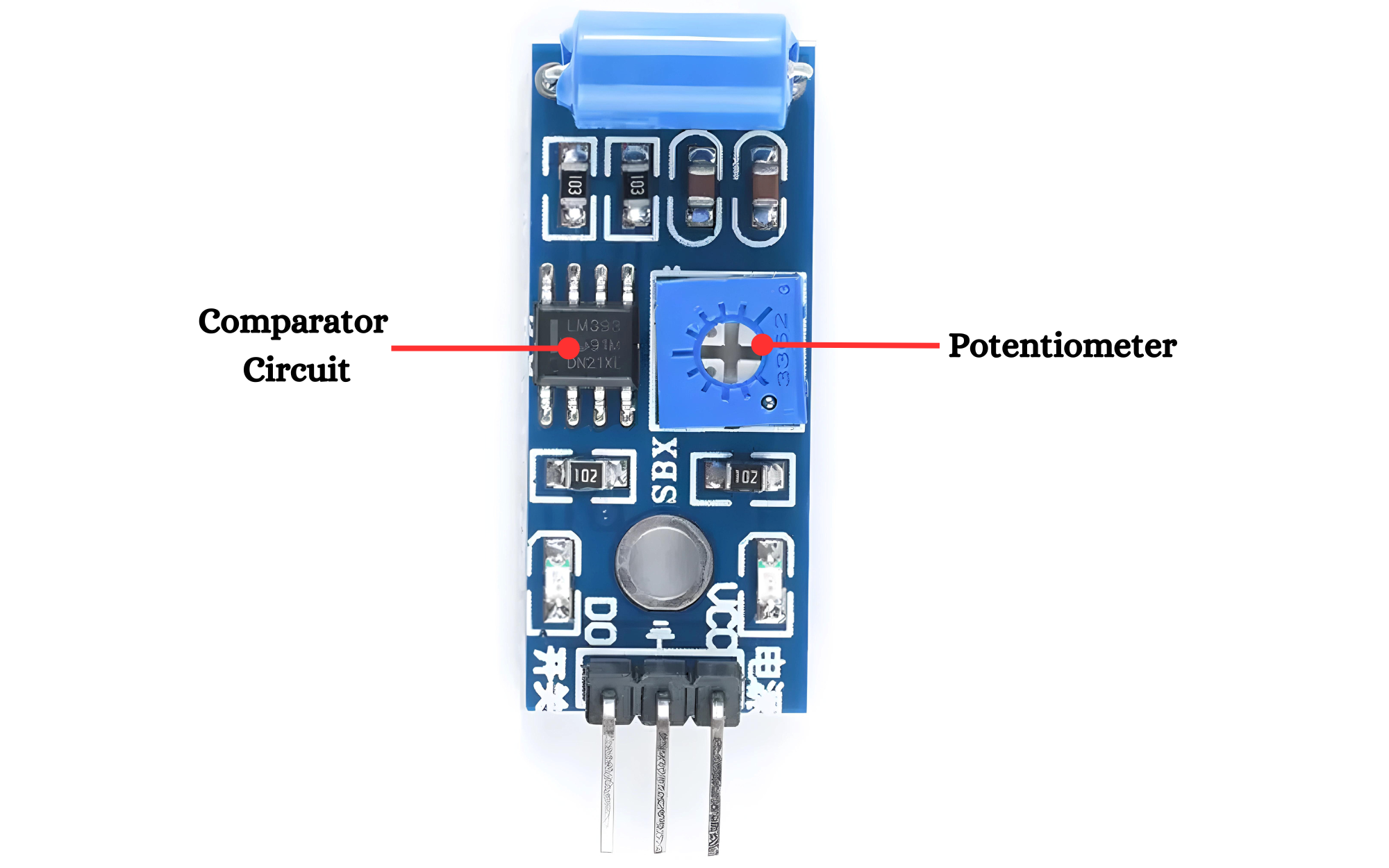
Comparator Circuit
- LM393 Comparator IC: This is the heart of the sensor’s signal conditioning circuit. It compares the input signal to a reference voltage and outputs a high or low signal based on the comparison.
Potentiometer:
- Variable Resistor: Adjusts the reference voltage.
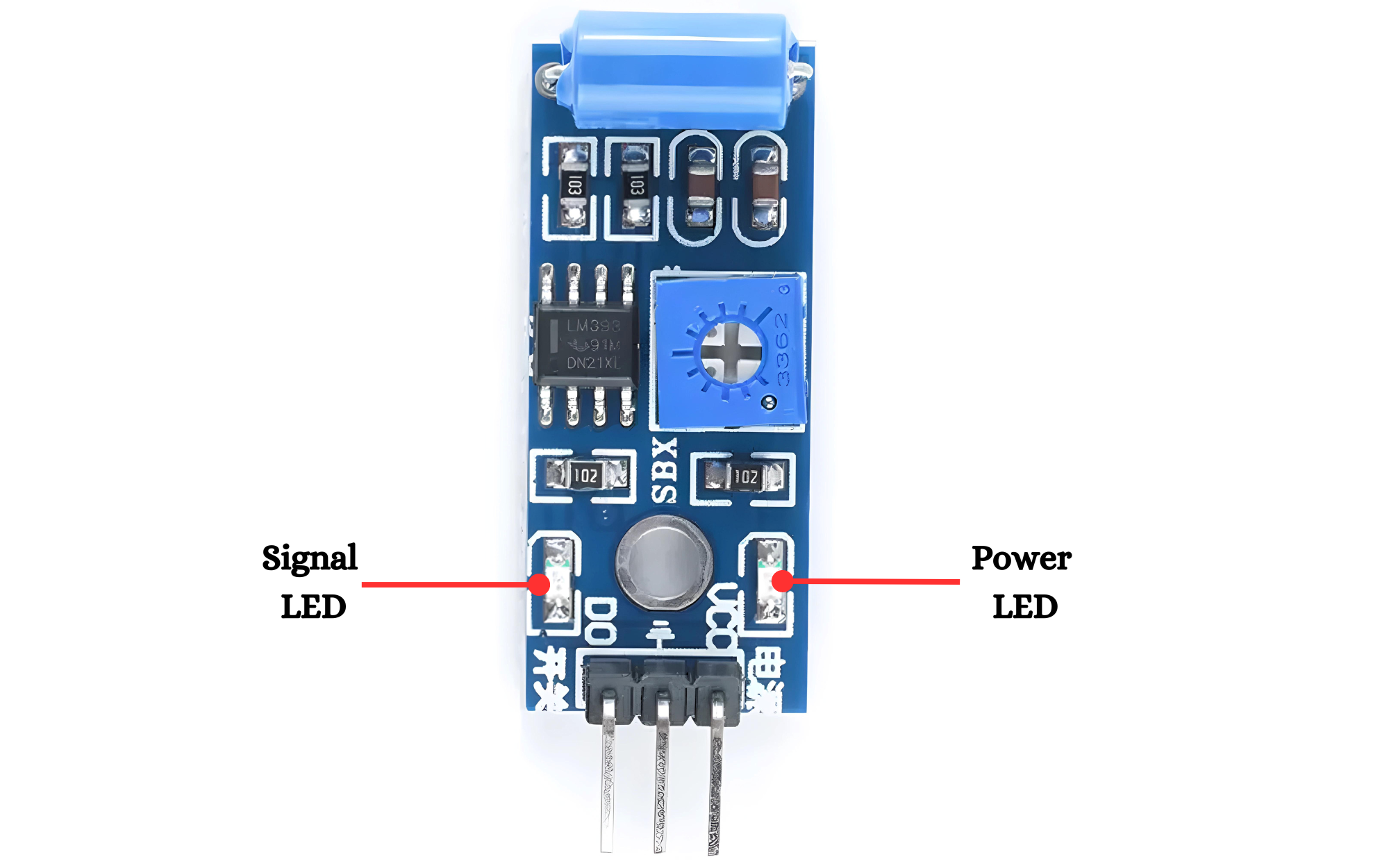
Power LED
- The Power LED indicates that the circuit is powered and operational. It is usually connected in parallel with the power supply to show the presence of voltage.
Signal LED
An LED that will light up when a vibration is detected. It has a forward voltage of about 2V and typically a current rating of 20mA.
Working Principle
The SW420 vibration sensor uses a spring-based mechanism to detect vibrations. When vibrations occur, the spring inside the sensor moves, causing changes in electrical contact. This change is detected by a comparator circuit, which outputs a digital signal based on the level of vibration detected. The sensor can be adjusted for sensitivity using an onboard potentiometer.
Application
- Motion Detection
- Vibration Monitoring
- Smart Devices
- Vehicle Security
- Consumer Electronics
Technical Specifications
- Using SW-420 normally closed type vibration sensor
- Operating voltage 3.3V ~ 5V
- Output format: digital switching output (0 and 1)
- Using a wide voltage LM393 comparator
- With bolt holes for easy installation
Pinout
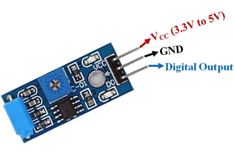
- VCC: Connect to the positive supply voltage (3.3V or 5V).
- OUT: Connect to a microcontroller or digital input/output pin to read the sensor output.
- GND: Connect to the ground (0V) of the power supply to complete the circuit.
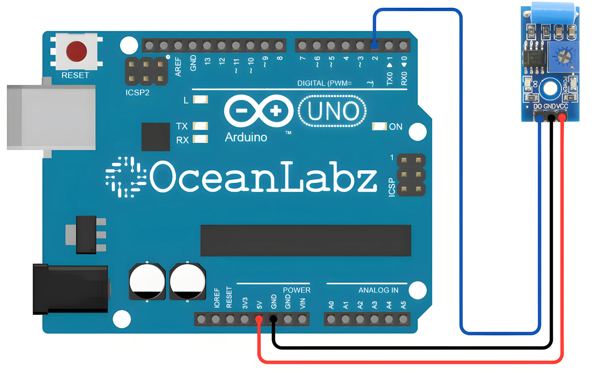
Circuit Diagram
| SW420 Pin | Aeduino Pin |
| VCC | 5 V |
| GND | GND |
| OUT | D2 |
Programming With Arduino
Step 1: Open your first sketch
- Open the Arduino IDE.
- Copy and paste the provided code into a new sketch in the Arduino IDE:
// Define the pin connections
const int sensorPin = 2;  // Connect the OUT pin of SW420 sensor to digital pin 2

void setup() {
  Serial.begin(9600);  // Initialize serial communication
  pinMode(sensorPin, INPUT);  // Set sensor pin as input
}

void loop() {
  // Read the sensor output (HIGH or LOW)
  int sensorValue = digitalRead(sensorPin);

  // Check if vibration is detected
  if (sensorValue == HIGH) {
    Serial.println("Vibration detected!");  // Print message to serial monitor
    // Add your code here to take action upon vibration detection
  }

  delay(100);  // Delay to stabilize readings
}
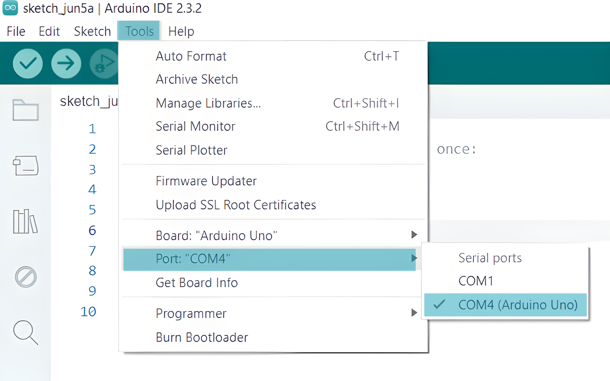
Step 2: Select your board type and port
- Go to Tools > Board and select your Arduino board (e.g., Arduino Uno).
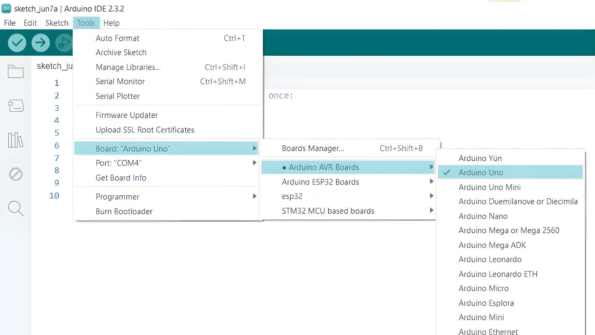
- Go to Tools > Port and select the port to which your Arduino is connected.
- Verify and upload the code to your Arduino board.

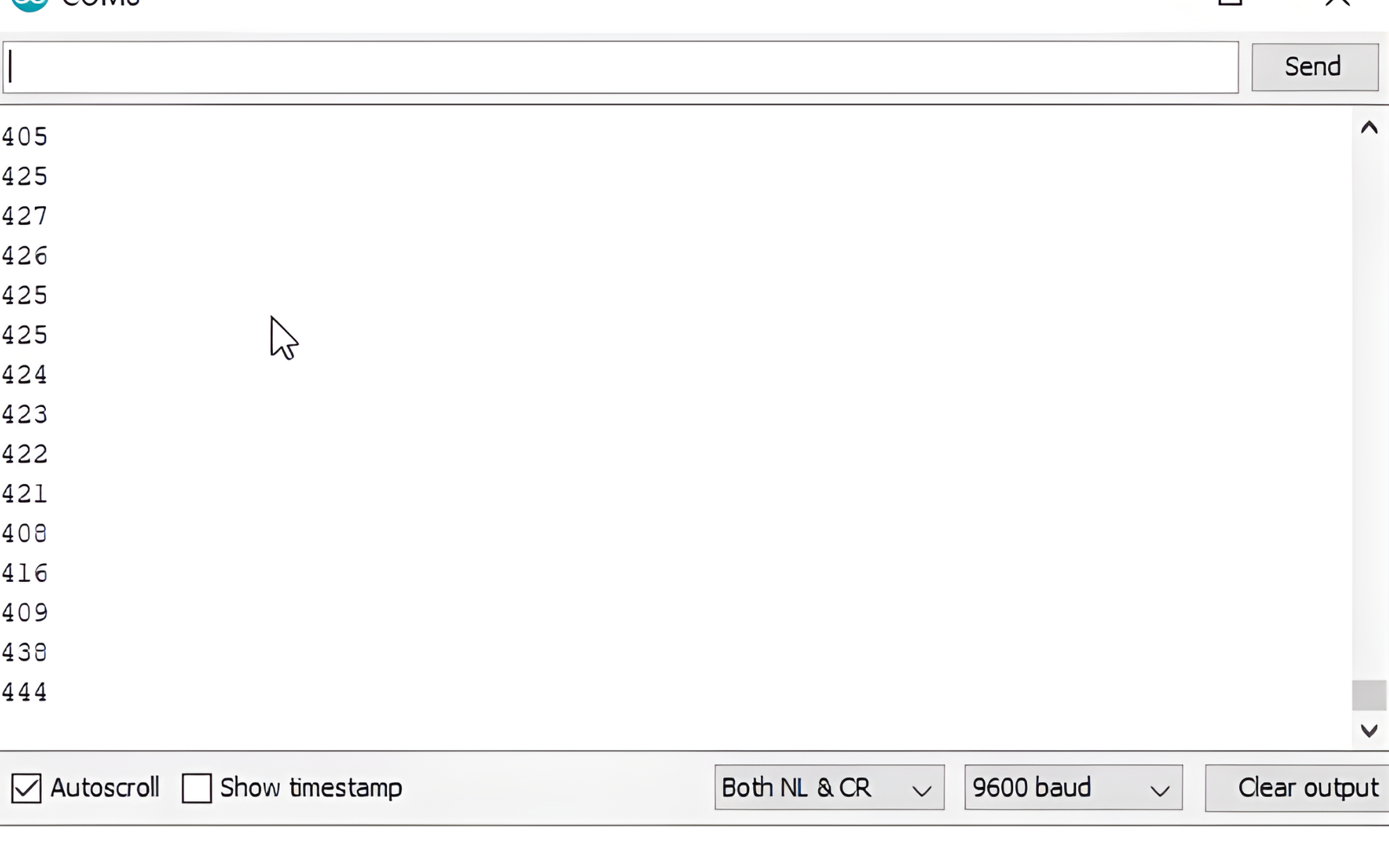
Step 3: Open Serial Monitor:
- Once the code is uploaded successfully, open the Serial Monitor in the Arduino IDE.
- Set the baud rate to 9600 baud.