Index
Introduction
A clap sensor is a type of sensor that detects sound or vibration and triggers an action in response. It is a simple and fun way to control devices with just a clap of your hands. In this blog, we will discuss what a clap sensor is, how it works, its technical specifications, and how to interface it with an Arduino.
Hardware Overview
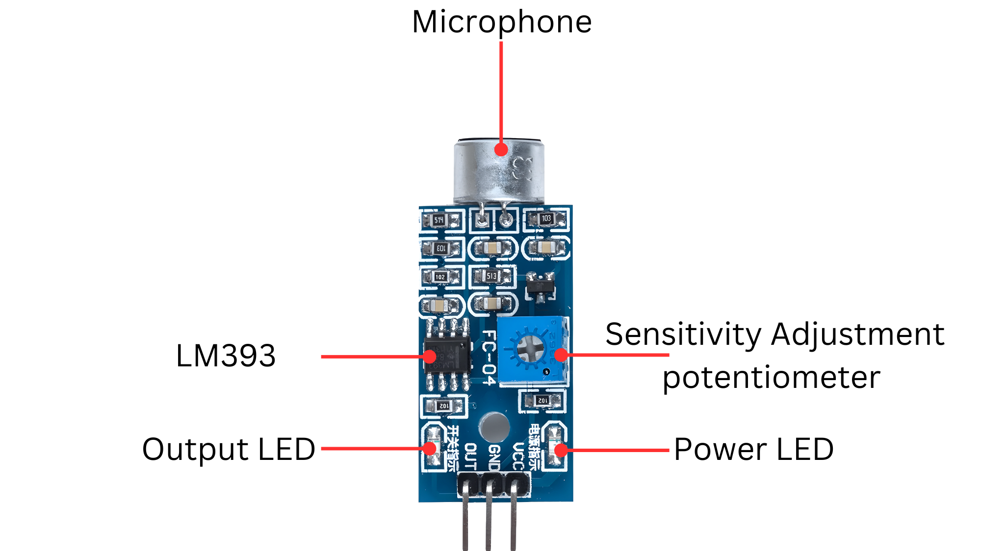
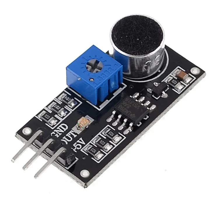
- Microphone: In a clap sensor system, the microphone is a critical component that detects the sound of clapping. It converts these sound waves into electrical signals, which are then amplified and processed by circuitry to detect the specific pattern of claps. This detection triggers a response, such as turning on a light or activating a device. The microphone’s sensitivity and frequency response are key factors in ensuring accurate detection of claps amidst background noise, making it essential for the system’s functionality and reliability.
- Sinsitivity Adjustment potentiometer:In a clap sensor system, a sensitivity adjustment potentiometer (pot) is often included to fine-tune the microphone’s sensitivity to detect claps effectively. Here’s how it works and its role in the system
Working Principle
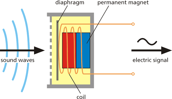
A Clap sensor, such as a microphone, operates by capturing sound waves (pressure variations in the air) and converting them into electrical signals. This conversion process involves a diaphragm within the sensor that vibrates in response to sound waves. The movement of this diaphragm mechanically alters a coil or capacitor inside the sensor, generating corresponding electrical signalsas shown below. These signals can then be processed further for tasks like audio recording, analysis, or noise detection. Essentially, the sound sensor transforms sound energy into usable electrical signals for various applications.
Application
- Speech Recognition: Enables voice commands in smart devices.
- Audio Recording: Captures sound for various purposes like music production and video recording.
- Noise Monitoring: Measures and detects noise levels in environments.
- Security Systems: Alerts to unusual sounds or disturbances.
- Automotive Applications: Used for hands-free calling and noise cancellation in vehicles.
- Industrial Automation: Detects abnormal sounds in machinery for maintenance alerts.
- Consumer Electronics: Integrated into devices for noise cancellation and voice control.
Technical Specifications
- Operating voltage 3.3V-5V
- Outputs digital switching output (high and low levels 0 and 1
- Operating current (Vcc=5V): 4-8mA
- Microphone sensitivity (1Khz): 52-48dB
- Microphone Impedance: 2.2KΩ
- Microphone Frequency: 16-20Khz
- Microphone S/N ratio: 54dB
- Signal output indication
- Single channel signal output
- Outputs low level and the signal light when there is sound
Pinout
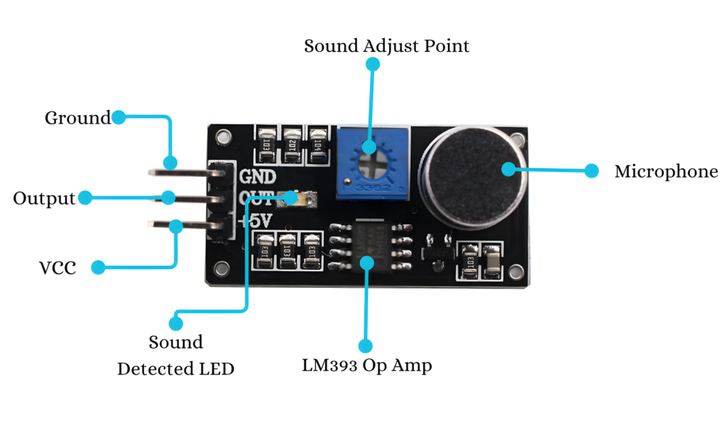
- VCC -> Arduino 5V
- GND -> Arduino GND
- OUT -> Arduino Analog (A0) or Digital (D3) input
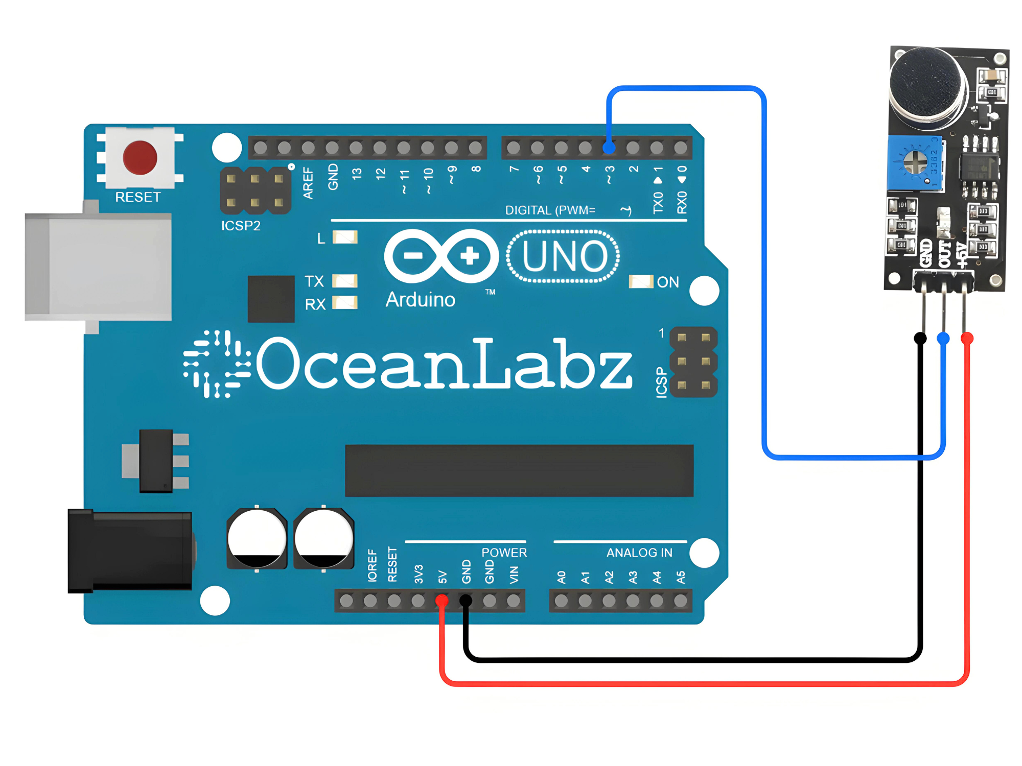
Circuit Diagram
| Clap Senosr Pin | Arduino Pin |
| VCC | 5 V |
| GND | GND |
| OUTPUT | D3 |
Code
const int soundSensorPin = 3;
void setup() {
  Serial.begin(9600);}

void loop() {
  int sensorValue = analogRead(soundSensorPin);
  Serial.println(sensorValue);
  delay(100); // Adjust delay time as needed
}