Index
Introduction

The DS3231 RTC module is a compact and precise timekeeping device designed to keep track of time, date, and day-of-the-week information. It incorporates a temperature-compensated crystal oscillator (TCXO) to ensure accurate timekeeping over a wide temperature range.
Hardware Overview
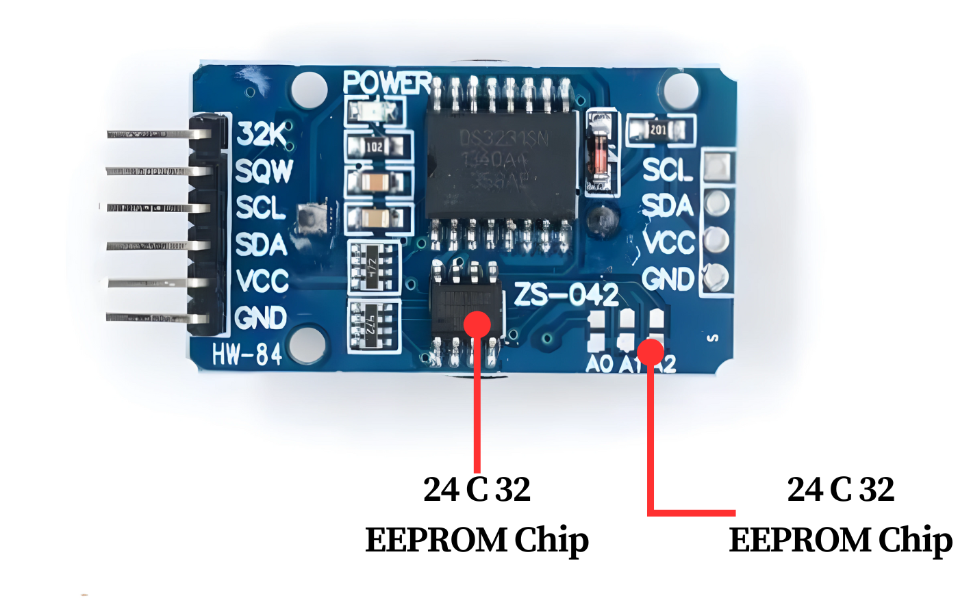
This module features the highly capable DS3231S RTC chip and the AT24C32 EEPROM, both of which are well-established components with excellent library support.
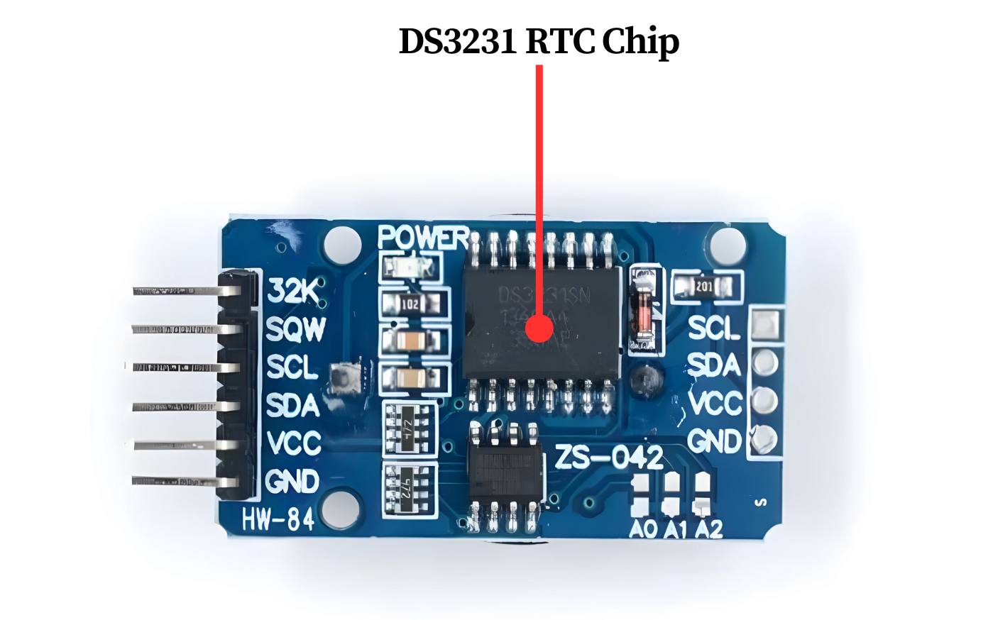
DS3231 RTC Chip
The core of the module is a low-cost, highly accurate RTC chip from Maxim, the DS3231. It manages all timekeeping functions and communicates with the microcontroller via I2C.
The DS3231 is capable of tracking seconds, minutes, hours, days, dates, months, and years. It automatically adjusts the date for months with fewer than 31 days, including leap year corrections, and is accurate until the year 2100.
The DS3231 supports both 12-hour and 24-hour formats and includes an AM/PM indicator. Additionally, it features two programmable time-of-day alarms.
The INT/SQW pin on the DS3231 can output either an interrupt signal triggered by alarm conditions or a square wave at frequencies of 1Hz, 4kHz, 8kHz, or 32kHz.
The DS3231 also provides a stable and accurate temperature-compensated reference clock on the 32K pin. This clock output can be useful in applications that require precise clock timing or for providing a clock signal to other circuits.
Temperature Compensated Crystal Oscillator(TCXO)
Many RTC modules, like the DS1307, need an external 32kHz crystal oscillator to maintain time. However, these crystals are sensitive to temperature variations, which can slightly alter their oscillation frequency over time, leading to cumulative inaccuracies.
To mitigate the effects of crystal drift, the DS3231 utilizes a 32kHz temperature-compensated crystal oscillator (TCXO). This oscillator is designed to withstand external temperature variations, ensuring more stable and accurate timekeeping.
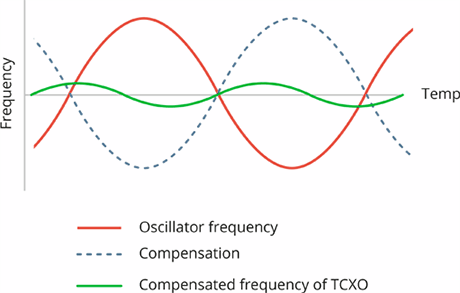
The TCXO consists of a built-in temperature sensor, a 32kHz crystal oscillator, and control logic. By detecting temperature variations, the integrated sensor adjusts the clock frequency accordingly, compensating for any deviations and maintaining precise timekeeping.
Due to its integrated temperature compensation and precise control, the TCXO offers the most reliable and precise reference clock. This ensures that the RTC maintains accuracy within a range of ±2 minutes per year.
Battery Backup
The DS3231 IC includes a battery input to ensure consistent timekeeping, even in the event of a power outage or interruption to the device’s primary power source.
The integrated power-sense circuit consistently monitors the VCC status to identify power disruptions and seamlessly transitions to the backup power source. This ensures uninterrupted timekeeping functionality, even during power failures.
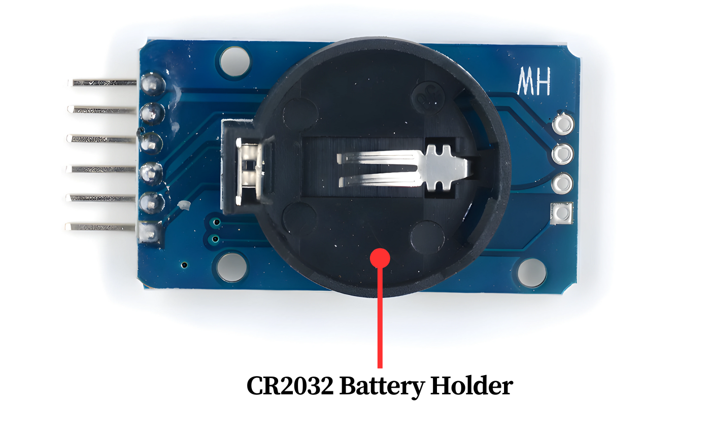
The underside of the board features a slot for a 20mm 3V lithium coin cell battery, providing backup power when needed.
Onboard 24C32 EEPROM
In addition to the DS3231 RTC module, there is a 32-byte (4K x 8-bits) AT24C32 EEPROM chip included. This non-volatile chip offers 1,000,000 write cycles and is independent of the RTC functionality. It can be utilized for tasks such as data logging or storing other non-volatile data.
The 24C32 EEPROM communicates through the I2C protocol and operates on the same I2C bus as the DS3231 RTC module.
When utilizing multiple devices on a single I2C bus, it might be necessary to assign a unique I2C address to the EEPROM to prevent interference with other I2C devices.
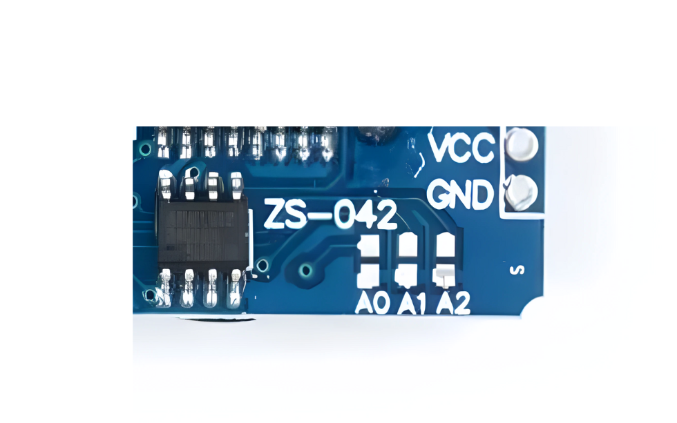
To configure the I2C address of the module, there are three solder jumpers (A0, A1, and A2) located on the back. By bridging a jumper with solder, you can set the desired address.
As specified in the datasheet for the 24C32, these three bits are positioned at the conclusion of the seven-bit I2C address, directly preceding the Read/Write bit.

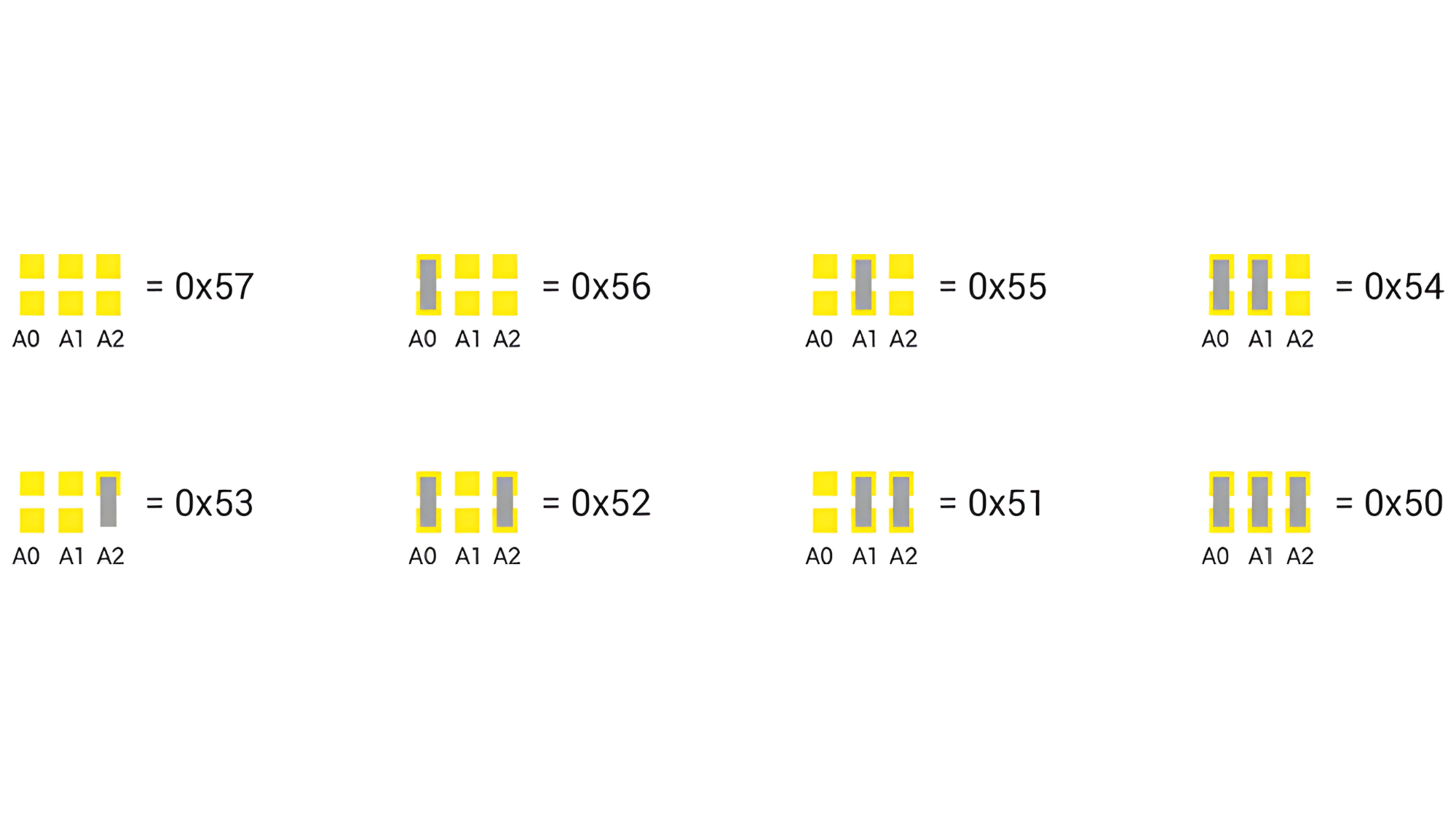
With three address inputs capable of being set to either a HIGH or LOW state, a total of eight (2^3) distinct addresses can be generated.
Out of the box, the 24C32 module sets all three address inputs to a HIGH state through built-in pull-up resistors. This configuration assigns the default I2C address of the device as 1010111 in binary or 0x57 in hexadecimal.
By connecting the solder jumpers, the address inputs are set to a LOW state. This enables you to adjust the I2C address as outlined in the provided table.
Application
- Electronic Clocks and Timers:
- Building digital clocks, timers, and countdown devices.
- Data Logging Systems:
- Recording timestamps for data logging applications.
- IoT Devices:
- Providing precise timekeeping for synchronization and event scheduling.
- Battery-Powered Devices:
- Maintaining timekeeping functionality in devices operating on battery power.
- Embedded Systems:
- Integrating into embedded systems for task scheduling and time-sensitive operations.
- Consumer Electronics:
- Incorporating into appliances, gadgets, and smart devices requiring accurate timekeeping.
Technical Specifications
- DS 3231 based RTC with 2032 Battery Holder.
- Voltage Supply: 2.2 V ~ 5.5 V (for RTC).
- Time Format: HH: MM: SS (12/24 hr).
- 1 Hz output pin SQW.
- 32 KHz output pin 32K.
- Date Format: YY-MM-DD.
Pinout
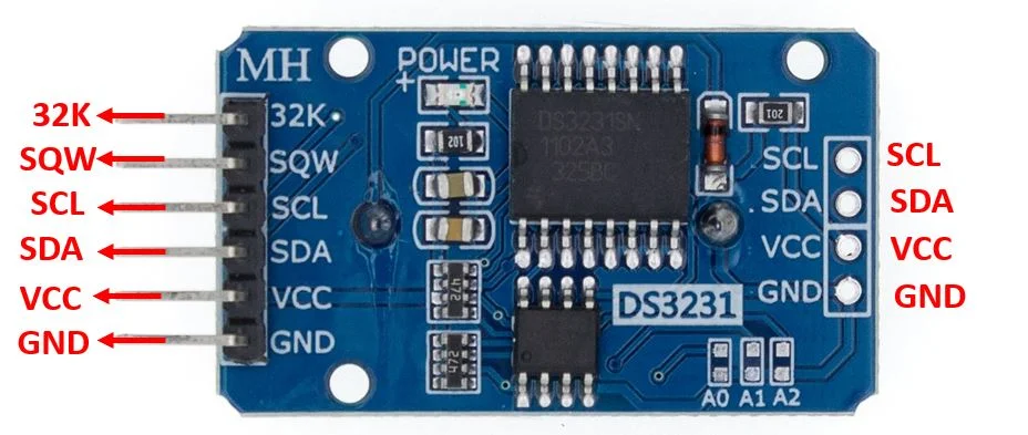
- VCC: Connects to a 3.3V – 5.5V power supply.
- GND: Ground connection.
- SCL: I2C clock line for communication with microcontrollers (e.g., Arduino).
- SDA: I2C data line for communication with microcontrollers.
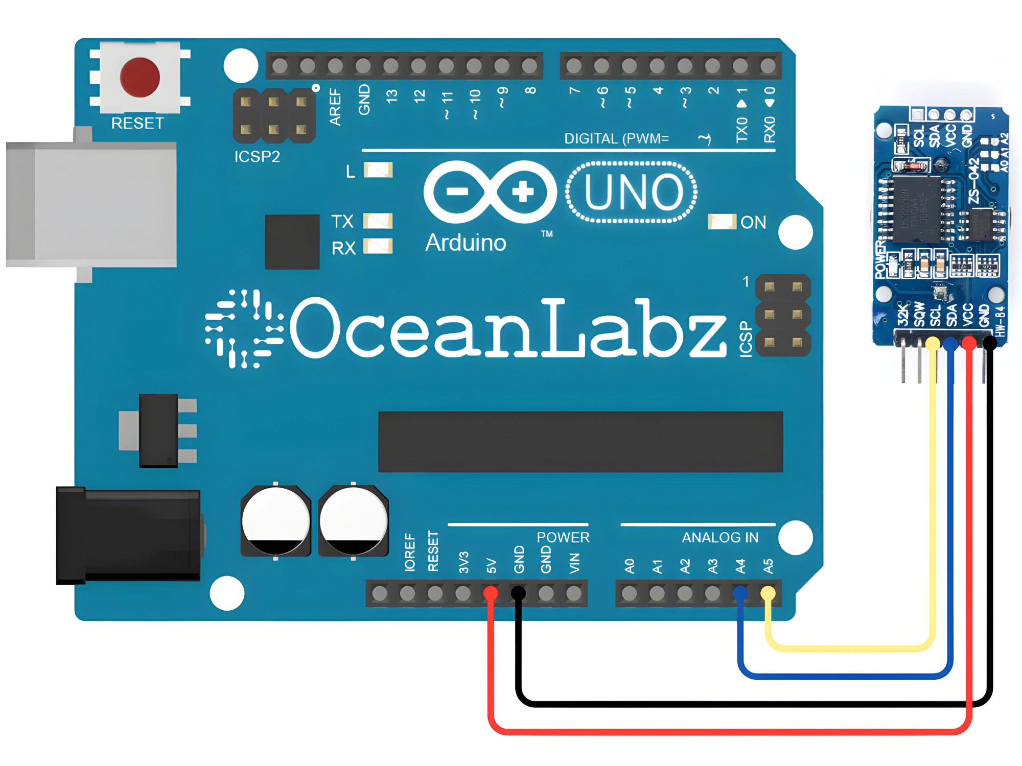
Circuit Diagram
| RTC Pin | Arduino Pin |
| VCC | 5 V |
| GND | GND |
| SDA | Analog A4 |
| SCL | Analog A5 |
Programming With Arduino
Step 1: Open your first sketch
- Open the Arduino IDE.
- Copy and paste the provided code into a new sketch in the Arduino IDE:
#include <Wire.h>
#include "RTClib.h"

// Create an RTC object
RTC_DS3231 rtc;

void setup() {
  // Start the serial communication
  Serial.begin(9600);
  // Initialize the RTC
  if (!rtc.begin()) {
    Serial.println("Couldn't find RTC");
    while (1);
  }

  // Check if the RTC lost power and if so, set the time
  if (rtc.lostPower()) {
    Serial.println("RTC lost power, let's set the time!");
    // The following line sets the RTC to the date & time this sketch was compiled
    rtc.adjust(DateTime(F(__DATE__), F(__TIME__)));
    // Alternatively, you can set the RTC with an explicit date & time
    // rtc.adjust(DateTime(2024, 5, 28, 15, 0, 0));
  }
}

void loop() {
  // Get the current date and time
  DateTime now = rtc.now();

  // Print the current date and time to the serial monitor
  Serial.print(now.year(), DEC);
  Serial.print('/');
  Serial.print(now.month(), DEC);
  Serial.print('/');
  Serial.print(now.day(), DEC);
  Serial.print(" ");
  Serial.print(now.hour(), DEC);
  Serial.print(':');
  Serial.print(now.minute(), DEC);
  Serial.print(':');
  Serial.print(now.second(), DEC);
  Serial.println();

  delay(1000);
}
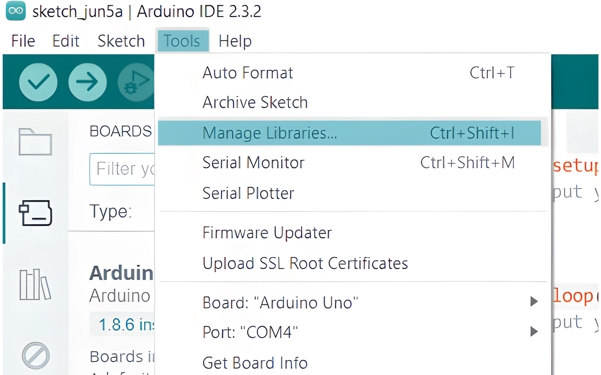
Step 2: Install the Required Libraries
- Go to
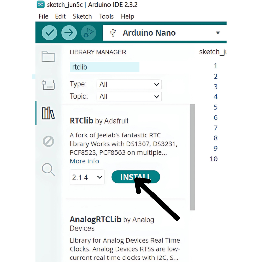
Sketch>Tools>Manage Libraries...In the Library Manager, search for “RTClib”.
- Install the “RTClib” library by Adafruit.
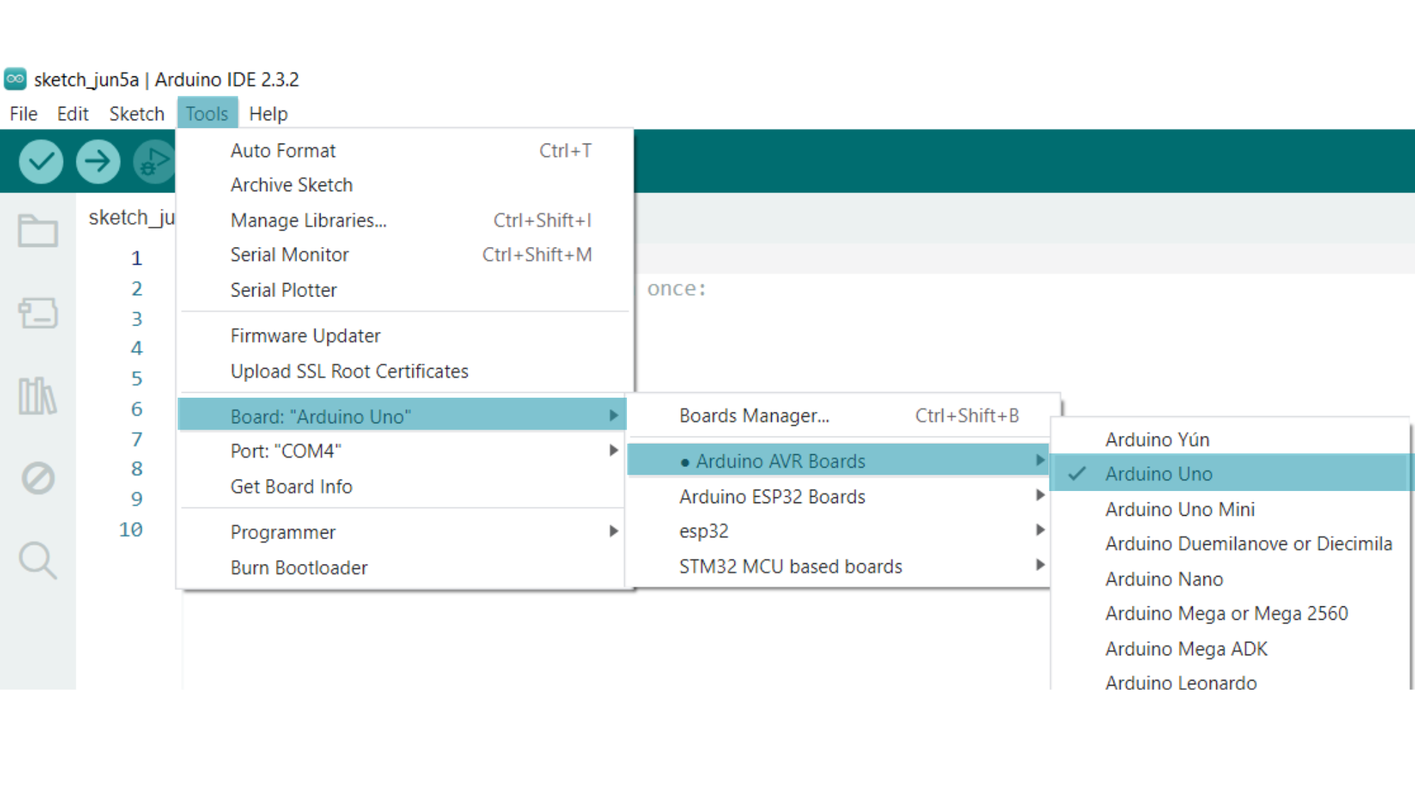
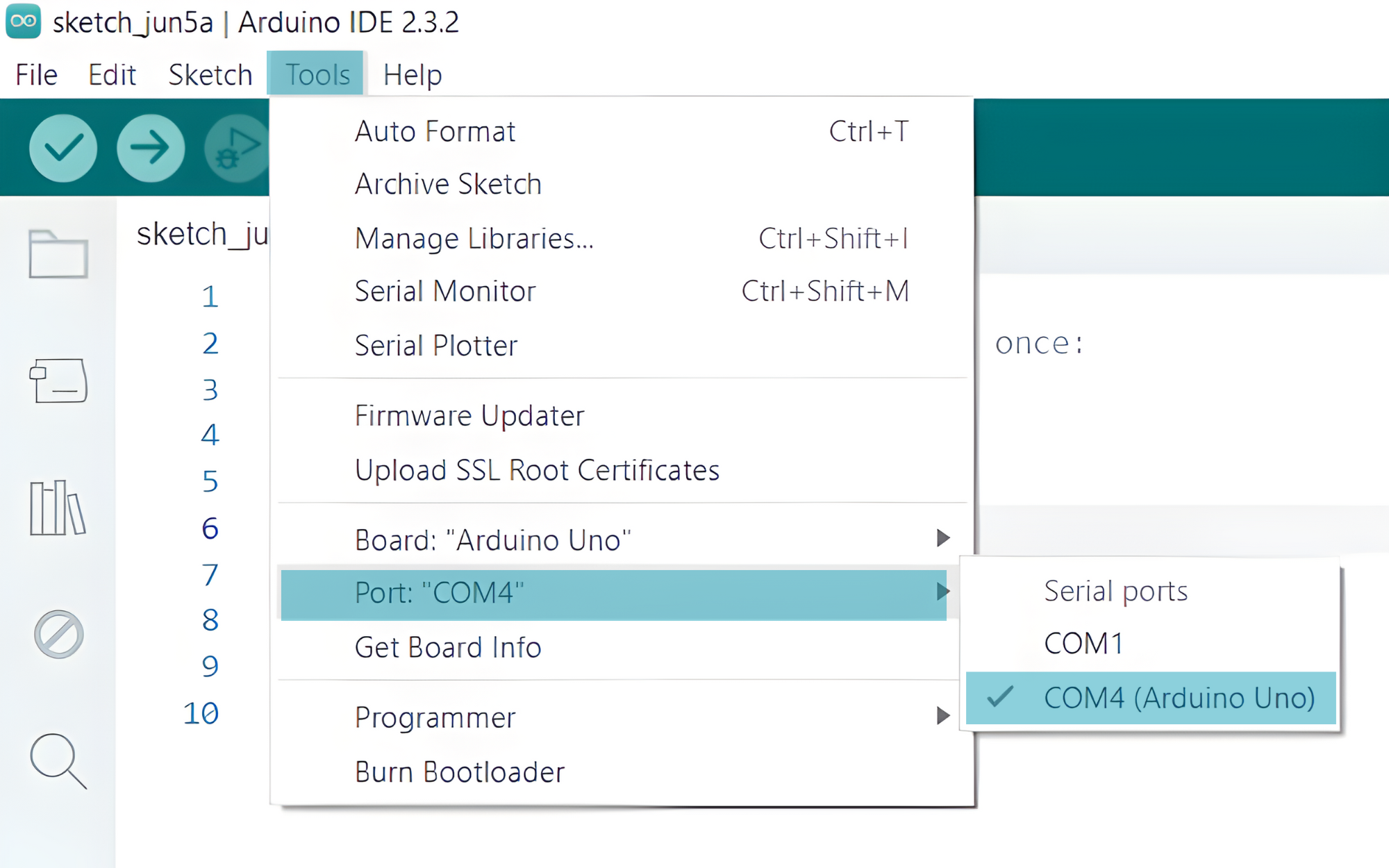
Step 3: Select your board type and port
- In the Arduino IDE, select your Arduino board from
Tools>Board.
- Select the serial device of the board from the Tools | Serial Port menu. This is likely to be COM3 or higher (COM1 and COM2 are usually reserved for hardware serial ports). To find out, you can disconnect your board and re-open the menu; the entry that disappears should be the Arduino board. Reconnect the board and select that serial port.
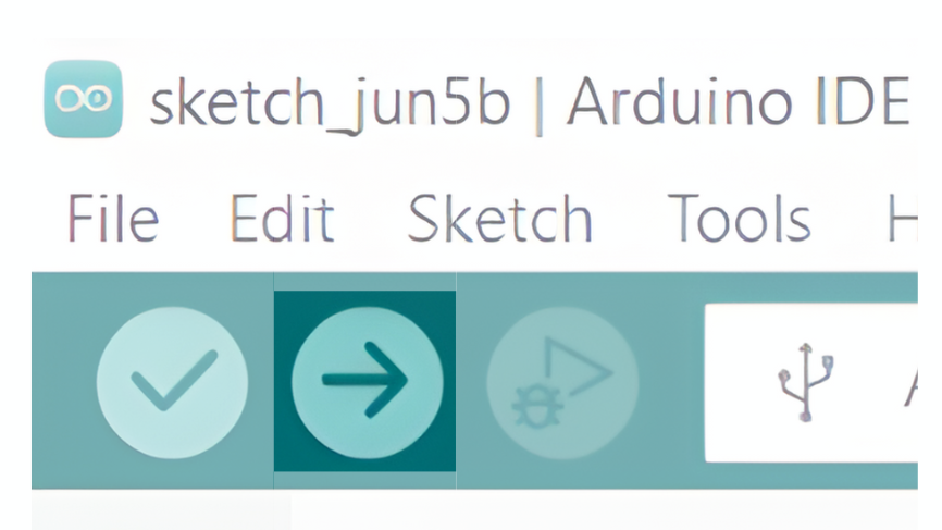
Step 4: Upload the Sketch
- Click the “Upload” button (right arrow icon) to upload the sketch to the Arduino.
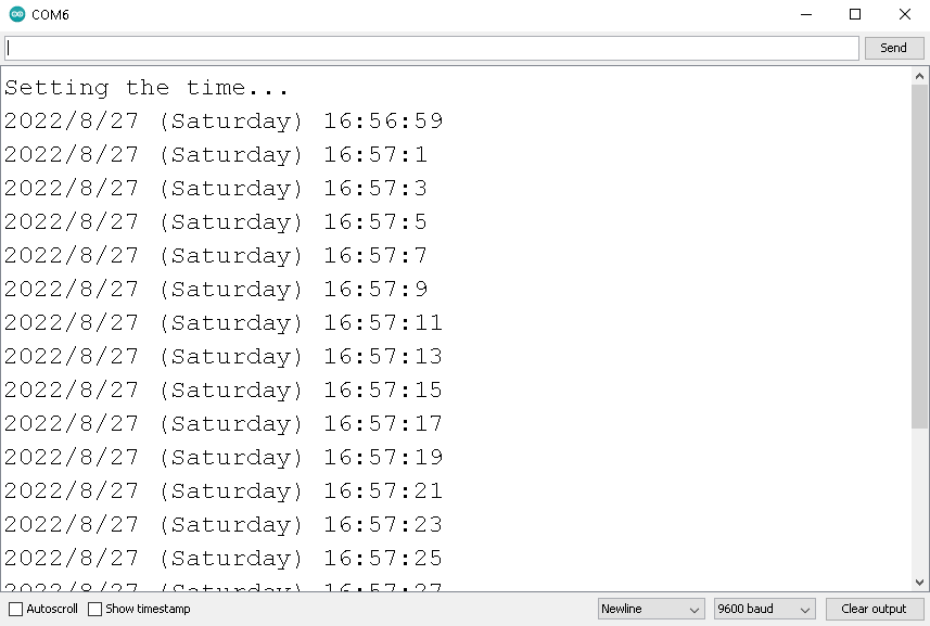
Step 6: Open the Serial Monitor
- After uploading the sketch, open the Serial Monitor in the Arduino IDE (Tools > Serial Monitor).
- Set the baud rate to 9600.
- You should see the current date and time being printed every second.