Index
Introduction
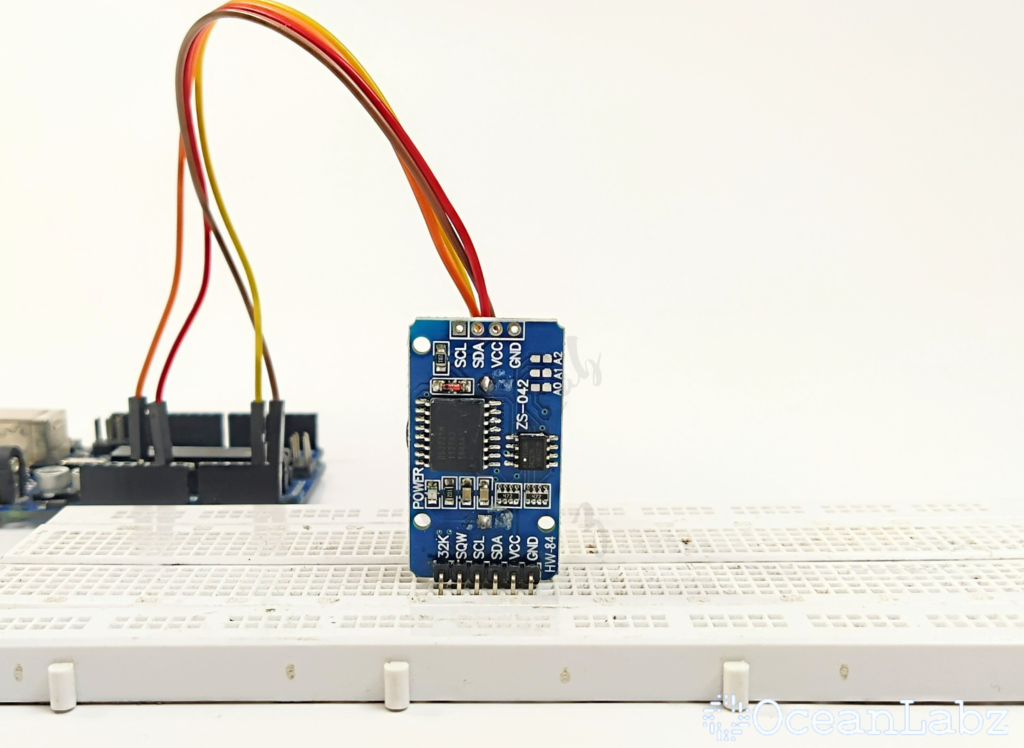
The DS3231 is a highly accurate real-time clock (RTC) module for Arduino, featuring an I2C interface for easy connectivity. It is ideal for applications requiring precise timekeeping, such as clocks and timers.Here’s a guide on reading the current date and time using Arduino with the DS3231 module.
Required Components
- Arduino Board (e.g., Arduino Uno)
- DS3231 RTC Module
- Jumper Wires
- Breadboard (optional)
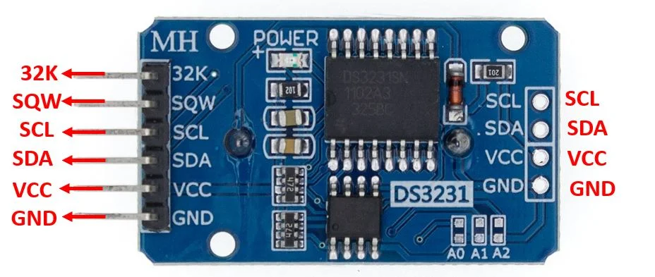
Pinout
Circuit Diagram / Wiring
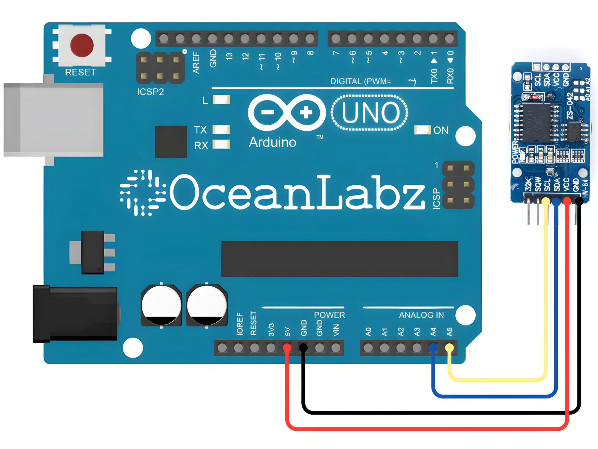
- RTC VCC → 5V (Arduino)
- RTC GND → GND (Arduino)
- RTC SDA → Pin A4 (Arduino)
- RTC SCL → Pin A5 (Arduino)
Programming With Arduino
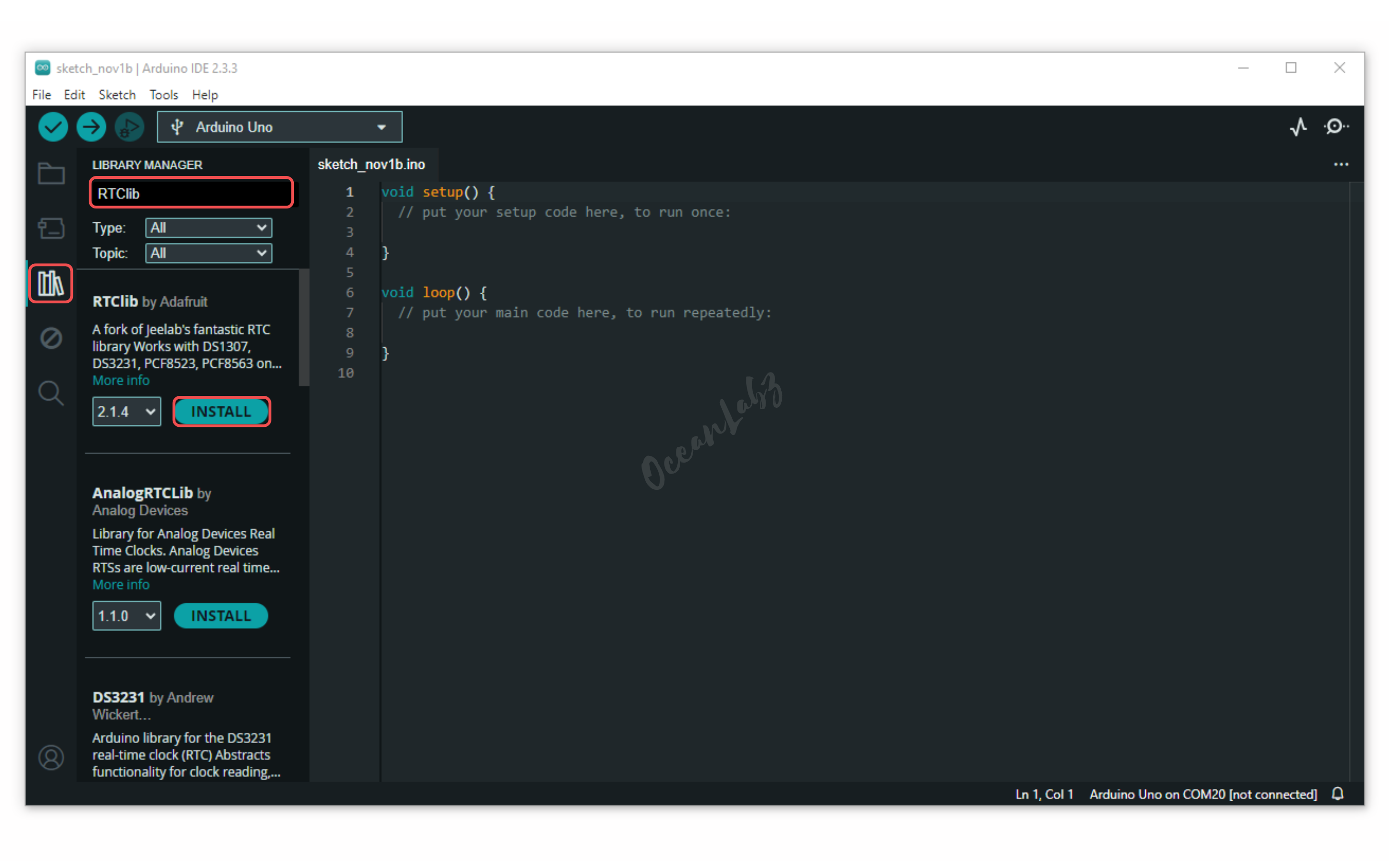
- Go to the “Libraries” tab on the left-hand side of the screen.
- Click on the “Library Manager” button (book icon) at the top of the Libraries tab.
- In the Library Manager window, type “RTClib” in the search bar, locate the RTClib library by Adafruit, and click on the “Install” button next to it.
- Copy and paste the provided code into a new sketch in the Arduino IDE:
#include <Wire.h>
#include "RTClib.h"

// Create an RTC object
RTC_DS3231 rtc;

void setup() {
  // Start the serial communication
  Serial.begin(9600);
  // Initialize the RTC
  if (!rtc.begin()) {
    Serial.println("Couldn't find RTC");
    while (1);
  }

  // Check if the RTC lost power and if so, set the time
  if (rtc.lostPower()) {
    Serial.println("RTC lost power, let's set the time!");
    // The following line sets the RTC to the date & time this sketch was compiled
    rtc.adjust(DateTime(F(__DATE__), F(__TIME__)));
    // Alternatively, you can set the RTC with an explicit date & time
    // rtc.adjust(DateTime(2024, 5, 28, 15, 0, 0));
  }
}

void loop() {
  // Get the current date and time
  DateTime now = rtc.now();

  // Print the current date and time to the serial monitor
  Serial.print(now.year(), DEC);
  Serial.print('/');
  Serial.print(now.month(), DEC);
  Serial.print('/');
  Serial.print(now.day(), DEC);
  Serial.print(" ");
  Serial.print(now.hour(), DEC);
  Serial.print(':');
  Serial.print(now.minute(), DEC);
  Serial.print(':');
  Serial.print(now.second(), DEC);
  Serial.println();

  delay(1000);
}
Explanation
- The code initializes a DS3231 RTC (Real-Time Clock) module with the Arduino to keep track of the current date and time.
- In the
setup()function, the RTC is checked for proper connection, and if it has lost power, it sets the time to the compilation date and time. - The
loop()function continuously retrieves the current date and time from the RTC and prints it to the Serial Monitor every second.
Testing and Troubleshooting
- Ensure the DS3231 RTC module is connected properly to the Arduino, checking the SDA and SCL pins as well as VCC and GND connections.
- If the message “Couldn’t find RTC” appears, double-check the wiring and the library installation to ensure compatibility with your module.
- If the time is not updating correctly, verify that the RTC has power and consider re-adjusting the time if it has lost power.
Arduino Projects:
Arduino Project 1 – Digital Alarm Clock with Rotary Encoder and OLED Screen
This project is a digital alarm clock that uses an OLED display, RTC module, and rotary encoder for time setting. It shows real-time updates of the current time, including seconds, day, and date. The rotary encoder enables easy adjustment of the alarm time. When the set alarm time is reached, a buzzer is triggered. The project offers an interactive and user-friendly experience for setting and managing alarms.
Required Components
- Arduino Board (e.g., Arduino Uno)
- DS3231 RTC Module
- OLED Display
- Buzzer Module
- Rotary Encoder
- Jumper Wires
- Breadboard
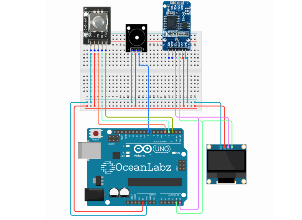
Circuit Diagram / Wiring
- RTC Module
- RTC VCC → 5V (Arduino)
- RTC GND → GND (Arduino)
- RTC SDA → Pin A4 (Arduino)
- RTC SCL → Pin A5 (Arduino)
- OLED Dispaly
- OLED VCC → 5V (Arduino)
- OLED GND → GND (Arduino)
- OLED SDA → Pin A4 (Arduino)
- OLED SCK → Pin A5 (Arduino)
- Rotary Encoder
- ROTARY VCC → 5V (Arduino)
- ROTARY GND → GND (Arduino)
- ROTARY CLK → Pin D2 (Arduino)
- ROTARY DT → Pin D3 (Arduino)
- ROTARY SW → Pin D4 (Arduino)
- Buzzer Module
- Buzzer VCC → 5V (Arduino)
- Buzzer GND → GND (Arduino)
- Buzzer Signal → Pin D8 (Arduino)
Arduino Code
#include <Wire.h>
#include <Adafruit_GFX.h>
#include <Adafruit_SSD1306.h>
#include <RTClib.h>

// OLED setup
#define SCREEN_WIDTH 128
#define SCREEN_HEIGHT 64
Adafruit_SSD1306 display(SCREEN_WIDTH, SCREEN_HEIGHT, &Wire, -1);

// RTC setup
RTC_DS3231 rtc;

// Rotary Encoder Pins
#define ROTARY_CLK 2
#define ROTARY_DT 3
#define ROTARY_SW 4

// Buzzer Pin
const int buzzerPin = 8;

// Variables for alarm setup
bool alarmSet = false;
int alarmHour = 0, alarmMinute = 0;
bool inAlarmSetup = false;
bool setHours = true;
int rotaryState = 0;

// Variables for rotary encoder
int lastCLKState;
unsigned long lastButtonPress = 0;

void setup() {
  Serial.begin(9600);

  // Initialize OLED
  if (!display.begin(SSD1306_SWITCHCAPVCC, 0x3C)) {
    Serial.println(F("SSD1306 allocation failed"));
    for (;;);
  }

  // Initialize RTC
  if (!rtc.begin()) {
    Serial.println(F("Couldn't find RTC"));
    while (1);
  }
  if (rtc.lostPower()) {
    rtc.adjust(DateTime(F(__DATE__), F(__TIME__))); // Set RTC to compile time
  }

  // Initialize rotary encoder
  pinMode(ROTARY_CLK, INPUT_PULLUP);
  pinMode(ROTARY_DT, INPUT_PULLUP);
  pinMode(ROTARY_SW, INPUT_PULLUP);

  // Initialize buzzer
   pinMode(buzzerPin, OUTPUT);
  // digitalWrite(BUZZER_PIN, LOW);

  lastCLKState = digitalRead(ROTARY_CLK);

  display.clearDisplay();
}

void loop() {
  checkRotaryInput();

  if (inAlarmSetup) {
    alarmSetupScreen();
  } else {
    displayHomePage();
    checkAlarmTrigger();
  }
}

// Function to check rotary encoder input
void checkRotaryInput() {
  int currentCLK = digitalRead(ROTARY_CLK);

  // Check for rotation
  if (currentCLK != lastCLKState) {
    if (digitalRead(ROTARY_DT) != currentCLK) {
      rotaryState++; // Clockwise rotation
    } else {
      rotaryState--; // Counter-clockwise rotation
    }
    adjustAlarmTime(); // Update alarm time in setup
  }
  lastCLKState = currentCLK;

  // Check for button press
  if (digitalRead(ROTARY_SW) == LOW) {
    if (millis() - lastButtonPress > 300) { // Debounce
      if (!inAlarmSetup) {
        inAlarmSetup = true; // Open alarm setup screen
        setHours = true;     // Start with setting hours
      } else if (setHours) {
        setHours = false; // Move to minutes setup
      } else {
        inAlarmSetup = false;
        alarmSet = true; // Confirm alarm setup
      }
      lastButtonPress = millis();
    }
  }
}

// Alarm setup screen
void alarmSetupScreen() {
  display.clearDisplay();

  display.setTextSize(1);
  display.setTextColor(SSD1306_WHITE);
  display.setCursor(0, 0);
  display.print("Set Alarm:");

  // Display current alarm time
  display.setTextSize(2);
  display.setCursor(30, 20);

  if (setHours) {
    display.setTextColor(SSD1306_BLACK, SSD1306_WHITE); // Highlight hours
    if (alarmHour < 10) display.print("0");
    display.print(alarmHour);
    display.setTextColor(SSD1306_WHITE);
    display.print(":");
    if (alarmMinute < 10) display.print("0");
    display.print(alarmMinute);
  } else {
    if (alarmHour < 10) display.print("0");
    display.print(alarmHour);
    display.print(":");
    display.setTextColor(SSD1306_BLACK, SSD1306_WHITE); // Highlight minutes
    if (alarmMinute < 10) display.print("0");
    display.print(alarmMinute);
    display.setTextColor(SSD1306_WHITE);
  }

  display.display();

  // Auto-save alarm after a short delay
  if (setHours == false) {
    if (millis() - lastButtonPress > 50000) { // Auto-save after 5 seconds
      inAlarmSetup = false;
      alarmSet = true;
    }
  }
}

// Adjust alarm time using rotary encoder
void adjustAlarmTime() {
  if (setHours) {
    if (rotaryState > 0) {
      alarmHour++;
      if (alarmHour > 23) alarmHour = 0;
    } else if (rotaryState < 0) {
      alarmHour--;
      if (alarmHour < 0) alarmHour = 23;
    }
  } else {
    if (rotaryState > 0) {
      alarmMinute++;
      if (alarmMinute > 59) alarmMinute = 0;
    } else if (rotaryState < 0) {
      alarmMinute--;
      if (alarmMinute < 0) alarmMinute = 59;
    }
  }
  rotaryState = 0; // Reset rotary state
}

// Display home page
void displayHomePage() {
  DateTime now = rtc.now();
  display.clearDisplay();

  // Top Bar: Day
  display.fillRect(0, 0, 128, 16, SSD1306_WHITE);
  display.setTextColor(SSD1306_BLACK);
  display.setTextSize(1);
  display.setCursor(4, 4);
  display.print(getDayOfWeek(now.dayOfTheWeek()));

  // Date
  display.setTextColor(SSD1306_WHITE);
  display.fillRect(0, 16, 128, 16, SSD1306_BLACK);
  display.setCursor(4, 20);
  display.print(monthName(now.month()));
  display.print(" ");
  display.print(now.day());
  display.print(suffixForDay(now.day()));
  display.print(", ");
  display.print(now.year());

  // Time with Seconds
  display.fillRect(0, 32, 128, 32, SSD1306_WHITE);
  display.setTextColor(SSD1306_BLACK);
  display.setTextSize(2);
  display.setCursor(12, 40);
  display.print(now.hour());
  display.print(":");
  if (now.minute() < 10) display.print("0");
  display.print(now.minute());
  display.print(":");
  if (now.second() < 10) display.print("0"); // Display seconds with leading zero if needed
  display.print(now.second());

  // Alarm Icon
  if (alarmSet) {
    display.setTextSize(1);
    display.setCursor(110, 4);
    display.setTextColor(SSD1306_BLACK);
    display.print("ALM");
  }

  display.display();
  delay(1000); // Update every second
}


 // Check if alarm time matches RTC time
void checkAlarmTrigger() {
  DateTime now = rtc.now();
  if (alarmSet && now.hour() == alarmHour && now.minute() == alarmMinute) {
    triggerAlarm();
  }
}


// Trigger the buzzer alarm
void triggerAlarm() {
  for (int i = 0; i < 30; i++) { // Buzzer beeps 30 times
    tone(buzzerPin, 1500, 500);
    delay(500);
    noTone(buzzerPin);
    delay(500);
  }
  alarmSet = false; // Reset alarm after trigger
}

// Helper functions
String getDayOfWeek(uint8_t day) {
  const char *days[] = {"Sunday", "Monday", "Tuesday", "Wednesday", "Thursday", "Friday", "Saturday"};
  return days[day];
}

String monthName(uint8_t month) {
  const char *months[] = {"JAN", "FEB", "MAR", "APR", "MAY", "JUN", "JUL", "AUG", "SEP", "OCT", "NOV", "DEC"};
  return months[month - 1];
}

String suffixForDay(int day) {
  if (day >= 11 && day <= 13) return "th";
  switch (day % 10) {
    case 1: return "st";
    case 2: return "nd";
    case 3: return "rd";
    default: return "th";
  }
}
Explanation
- RTC Module: The RTC (Real-Time Clock) module is used to keep track of the current time and date. The
rtc.now()function retrieves the time, and it’s displayed on the OLED screen. - OLED Display: The OLED screen shows the time, date, and day of the week. It updates every second to reflect the current time and displays an alarm icon if the alarm is set.
- Rotary Encoder: The rotary encoder is used to adjust the alarm time. It controls the hours and minutes based on rotation direction (clockwise or counterclockwise). The button press toggles between setting hours and minutes.
- Alarm Setup: When the rotary encoder button is pressed, the user can enter alarm setup mode. After adjusting the time, the alarm is saved, and once the current time matches the alarm time, the buzzer will trigger.
- Buzzer: The buzzer beeps when the alarm time matches the current time. The buzzer will sound for 30 beeps, indicating the alarm has triggered, and then it resets.


