Index
Introduction
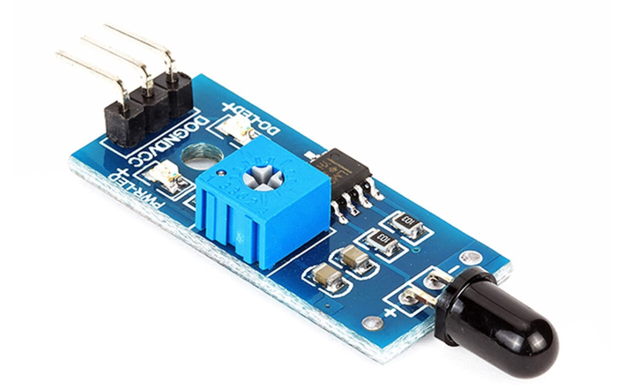
A Flame Sensor, also known as a flame detector or fire sensor, is a specialized sensor designed to detect the presence of flames or fire. It plays a crucial role in fire safety systems by providing early detection of fires or flames, which allows for prompt response measures to mitigate potential hazards. Here’s an introduction to flame sensors:
Hardware Overview
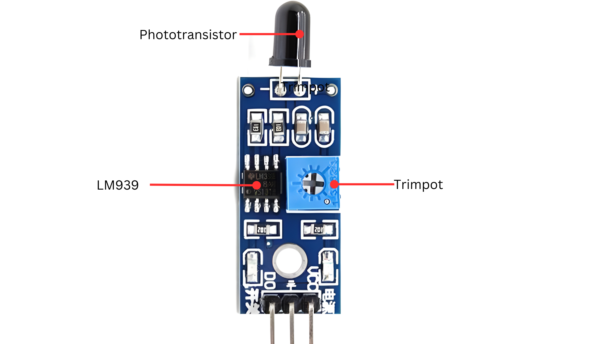
- Function: A phototransistor is a type of light-sensitive semiconductor device that detects light and converts it into an electrical signal. It operates similarly to a regular transistor but uses light instead of electrical signals to control current flow between its terminals.
- The LM393: is a widely used dual comparator integrated circuit (IC) that can also be relevant in the context of flame sensors, especially in applications where precise comparison of signals is required. Here’s an overview of the LM393 IC and its potential role in a flame sensor system:
- Sensitivity Adjustment: A trimpot can be used to adjust the sensitivity of the sensor circuitry. For example, in a UV flame sensor using a phototransistor, the trimpot could adjust the threshold at which the sensor detects UV light emitted by the flame.
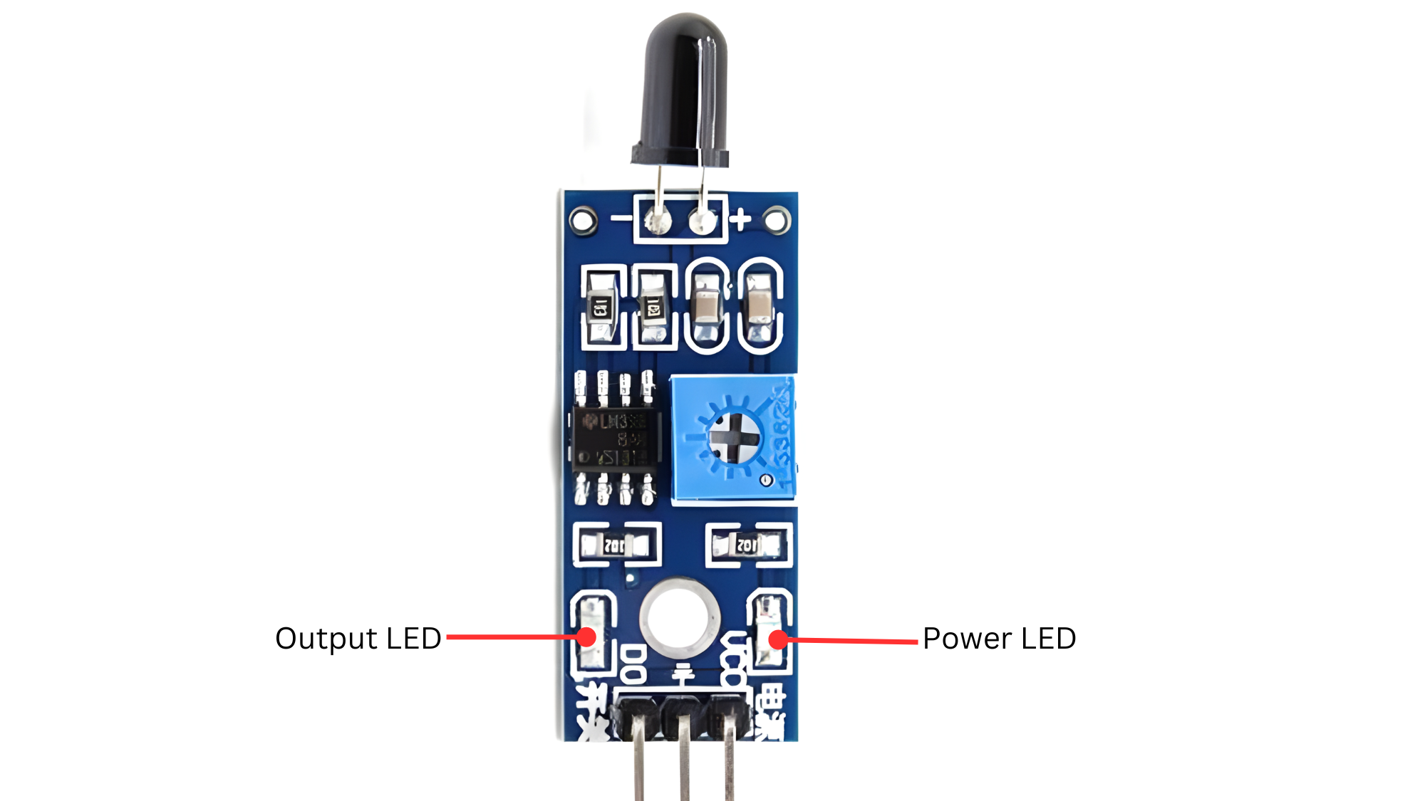
- Output LED: An output LED (Light Emitting Diode) in the context of a flame sensor serves as a visual indicator to provide immediate feedback about the status of the flame detection system. Here’s how an output LED is typically used and its significance:
ChatGPT
- Power LED: The power LED in a flame sensor system, or any electronic device, serves a fundamental role in indicating the operational status of the power supply. Here’s how the power LED is used and its significance in such systems:
Working Principle
Flame sensors are equipped with IR or UV sensors that can identify the unique light signatures emitted by flames. When a flame is present, it emits light in specific wavelengths within the IR or UV spectrum. The sensor is designed to recognize these characteristic wavelengths associated with flames, distinguishing them from background light sources. Upon detecting the signature of a flame, the sensor generates an electrical signal, which can be used to activate alarms, trigger safety systems, or initiate other responses. By filtering out non-flame sources of IR or UV light, such as sunlight or artificial lighting, flame sensors minimize false alarms and provide reliable flame detection in various applications.
Application
- Fire Alarm Systems: Integrated into fire alarm systems to detect flames and trigger alerts for early fire detection.
- Industrial Safety: Used in industrial settings to monitor combustion processes and activate safety measures in case of fire.
- Building Automation: Incorporated into building automation systems for fire detection and emergency response.
- Vehicle Safety: Implemented in vehicles to detect engine fires or other fire hazards.
- Robotics: Utilized in robotics for fire detection to enhance safety in automated systems.
- Consumer Electronics: Integrated into household appliances or gadgets for fire safety monitoring.
Technical Specifications
- Operating voltage 3.3V-5V.
- Comparator chip LM393 makes module readings stable.
- Fast Response Time
- Sensitivity adjustable
- Detects a flame or a light source of a wavelength in the range of 760nm-1100 nm.
- Detection range: up to 100 cm.
- Adjustable detection range.
- Detection angle about 60 degrees, it is sensitive to the flame spectrum.
Pinout

- VCC: Connects to a positive voltage supply (e.g., 5V or 3.3V).
- GND: Connects to the ground (0V) of the power supply.
- OUT: Outputs a digital signal indicating the presence of a flame (HIGH when flame detected, LOW otherwise).
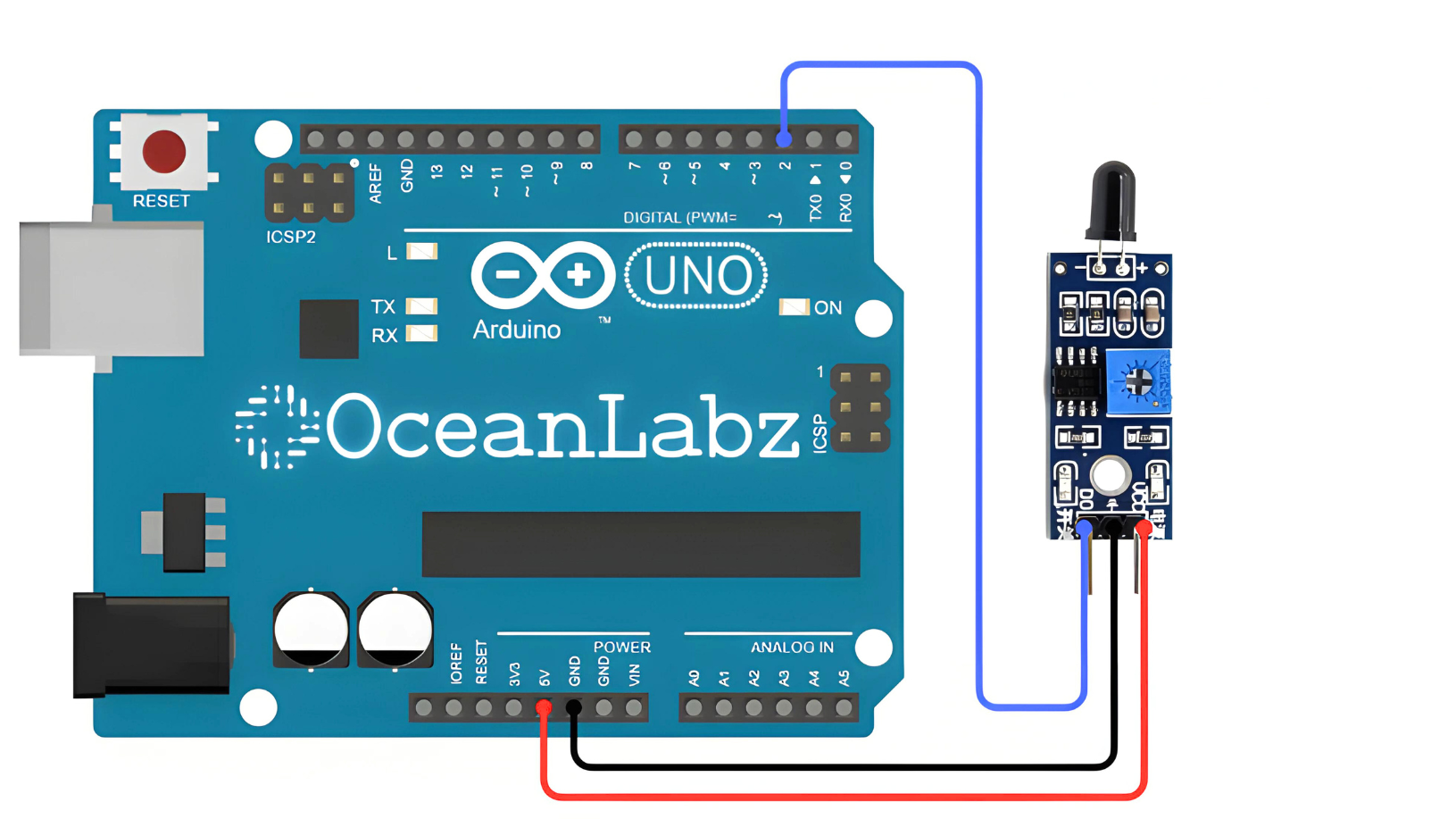
Circuit Diagram
| Flame sensor Pin | Arduino Pin |
| VCC | 5 V |
| GND | GND |
| OUT | D2 |
Programming With Arduino
Step 1: Open your first sketch
- Open the Arduino IDE.
- Copy and paste the provided code into a new sketch in the Arduino IDE:
Code
// Define flame sensor pin
const int flamePin = 2;  // Connect OUT pin of flame sensor to digital pin 2

void setup() {
  Serial.begin(9600);  // Initialize serial communication
  pinMode(flamePin, INPUT);  // Set flame sensor pin as input
}

void loop() {
  // Read flame sensor output
  int flameDetected = digitalRead(flamePin);

  // Check if flame is detected (sensor output is HIGH)
  if (flameDetected == HIGH) {
    Serial.println("Flame detected!");
  } else {
    Serial.println("No flame detected.");
  }

  delay(1000);  // Delay for 1 second before next reading
}
Step 2: Select your board type and port
- Go to Tools > Board and select your Arduino board (e.g., Arduino Uno).

- Go to Tools > Port and select the port to which your Arduino is connected.
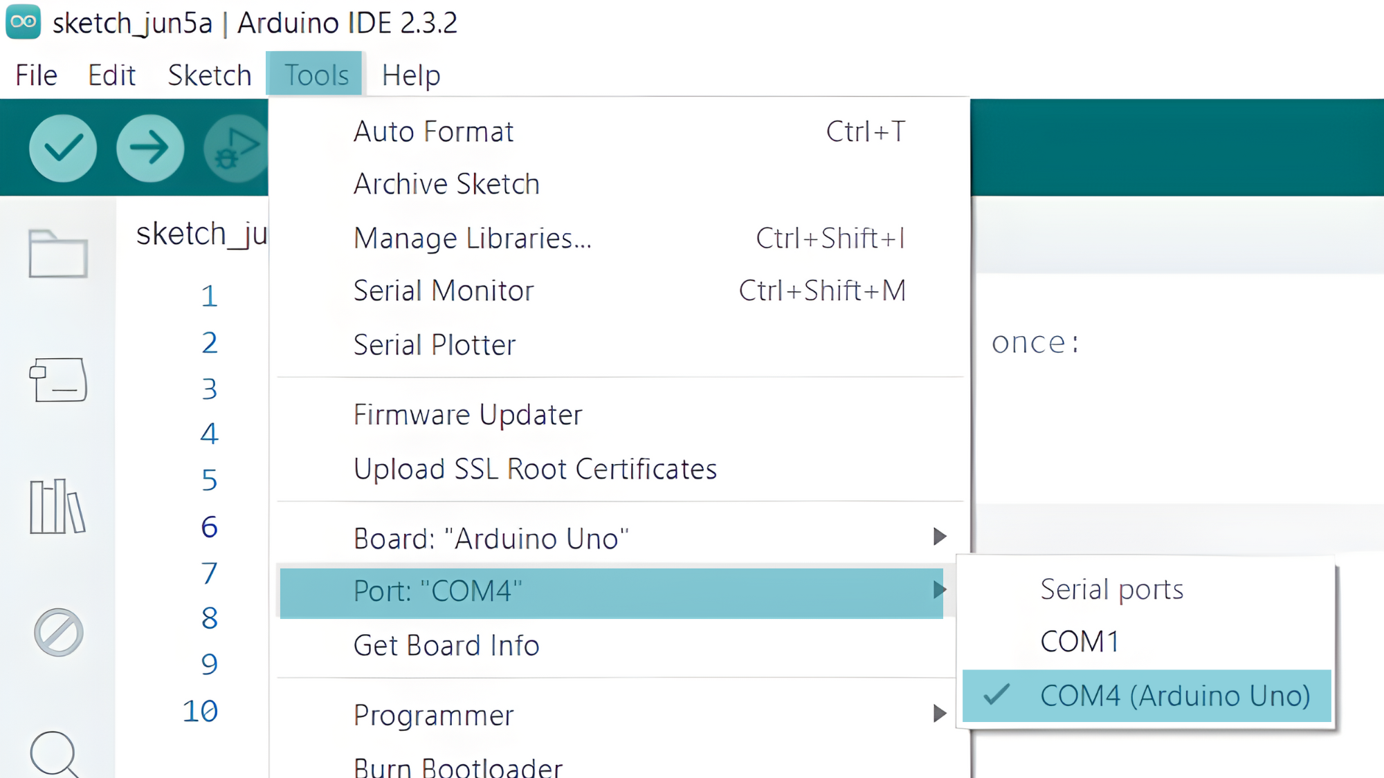
- Verify and upload the code to your Arduino board.

Step 3: Open Serial Monitor:
- Once the code is uploaded successfully, open the Serial Monitor in the Arduino IDE.
- Set the baud rate to 9600 baud.

