Index
Introduction
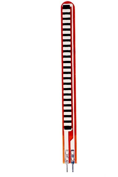
A flex sensor is a type of sensor that detects and measures the bending or flexing of a material, typically a thin film or strip of a flexible material. It is commonly used to measure the degree of bending in applications where monitoring the bending angle or curvature is important.
Working Principle
The conductive ink on the sensor serves as a resistor. When the sensor is straight, this resistance is around 25k.
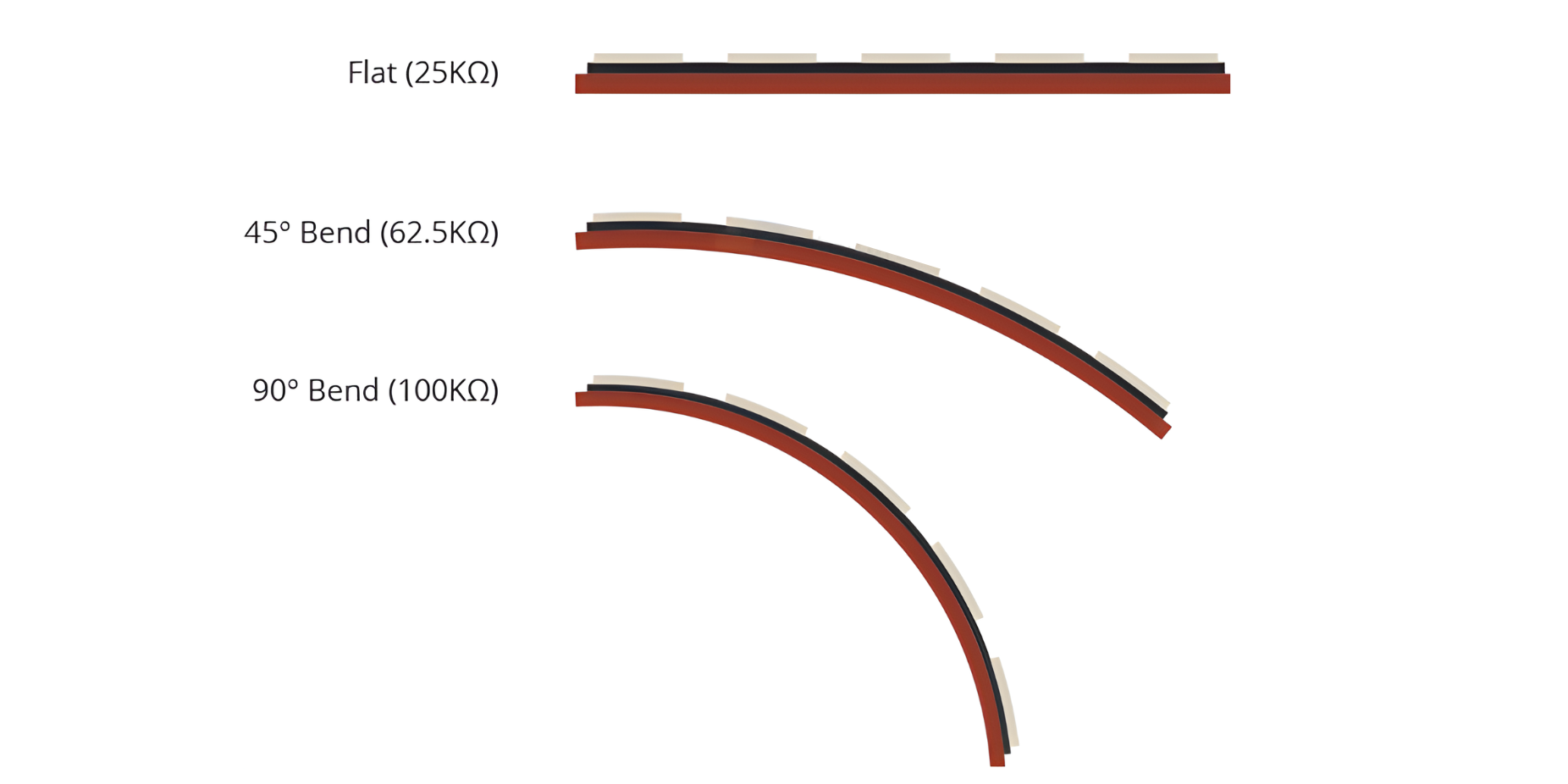
When the sensor is bent, the conductive layer is stretched, resulting in a reduced cross section (imagine stretching a rubber band) and increased resistance. At a 90° angle, this resistance is approximately 100K.
When the sensor is straightened out again, the resistance returns to its original value. By measuring the resistance, you can determine how much the sensor is bent.
Application
- Wearable Technology: Monitoring joint movement and gestures in wearable devices.
- Robotics: Control and feedback for robotic joints and limbs.
- Gaming Controllers: Enhancing interaction and control in gaming devices.
- Medical Devices: Monitoring muscle movement and prosthetic control.
- Industrial Automation: Position sensing in machinery and equipment.
- Musical Instruments: Adding expressive control to musical interfaces.
Technical Specifications
- Type: Resistance-based or capacitive.
- Bending Range: Degree of bending or curvature measurable by the sensor.
- Sensitivity: Responsiveness to bending (ohms/degree for resistance-based, capacitance change/degree for capacitive).
- Operating Voltage: Voltage range required for sensor operation.
- Size: Physical dimensions of the sensor (length, width, thickness).
- Durability: Number of bending cycles the sensor can withstand.
- Output Interface: Analog voltage or digital signal output.
Pinout
- Pin 1: One end of the flex sensor.
- Pin 2: The other end of the flex sensor.
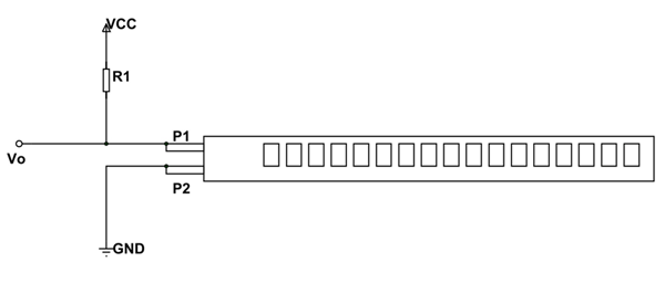
When using a flex sensor, you typically connect Pin 1 and Pin 2 to a voltage source (such as 5V) and ground, respectively. Then, you measure the resistance across Pin 1 and Pin 2 to determine the degree of flexion. The resistance changes as the sensor bends, providing a variable output that can be measured using an analog input on a microcontroller.
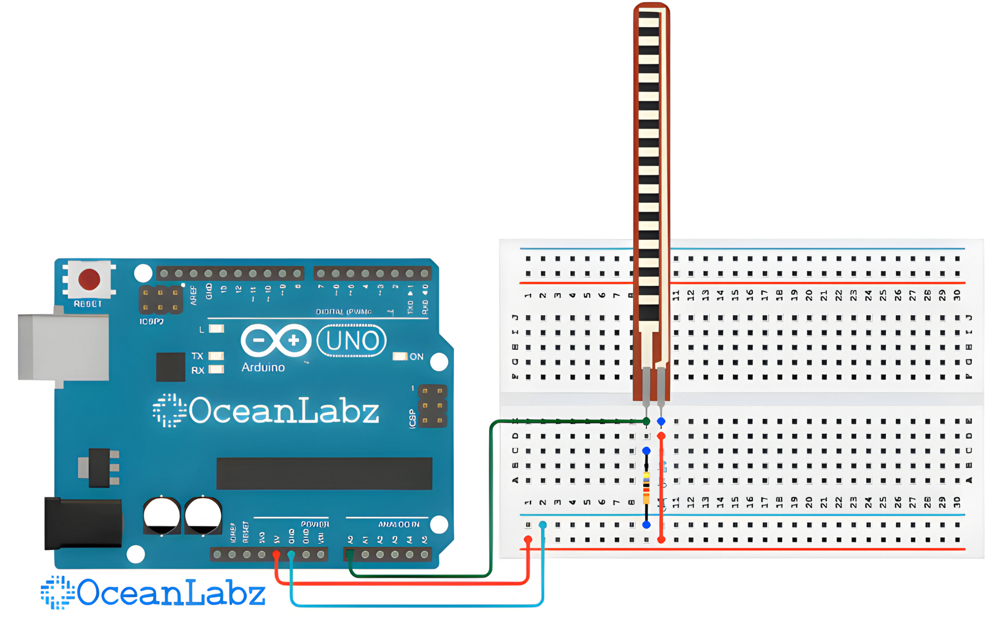
Circuit Diagram
| Flex Sensor Pin | Arduino Pin |
| Pin 1 | Analog A0 |
| Pin 2 | GND |
Programming With Arduino
Step 1: Select the appropriate board and port
- Go to Tools > Board and select your Arduino board (e.g., Arduino Uno).

- Go to Tools > Port and select the port to which your Arduino is connected.

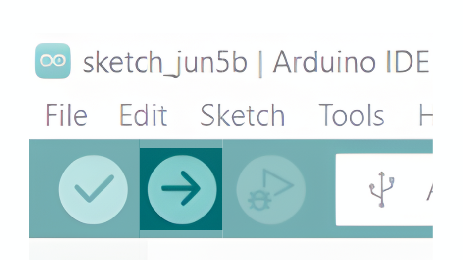
Step 2: Upload the Code
- Copy the provided code into your Arduino IDE.
const int flexSensorPin = A0; void setup() {
  Serial.begin(9600);
}

void loop() {
  int sensorValue = analogRead(flexSensorPin);

  Serial.println(sensorValue);

  delay(100); // Adjust delay time as needed
}
- Verify and upload the code to your Arduino board.
Step 3: Open the Serial Monitor
- Connect your Arduino to the computer and upload the code.
- Open the Serial Monitor in the Arduino IDE by going to Tools > Serial Monitor or pressing
Ctrl+Shift+M. - Set the baud rate to 9600 in the Serial Monitor.
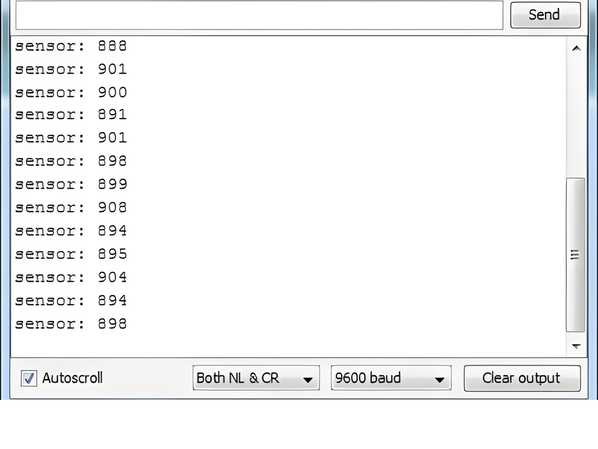
Observe the Output
- The Serial Monitor will display the sensor values read from the flex sensor.
- Bend the flex sensor and observe how the values change in the Serial Monitor.