Index
Introduction
PIR (Passive Infrared) motion sensor is a device that detects motion by measuring changes in infrared radiation emitted by nearby objects, such as humans or animals. When motion is detected, the sensor outputs a signal that can be used to trigger alarms, lights, or other actions in electronic systems. PIR sensors are commonly used in security systems, automatic lighting systems, and various types of motion-activated devices due to their simplicity, reliability, and low power consumption.
Hardware Overview
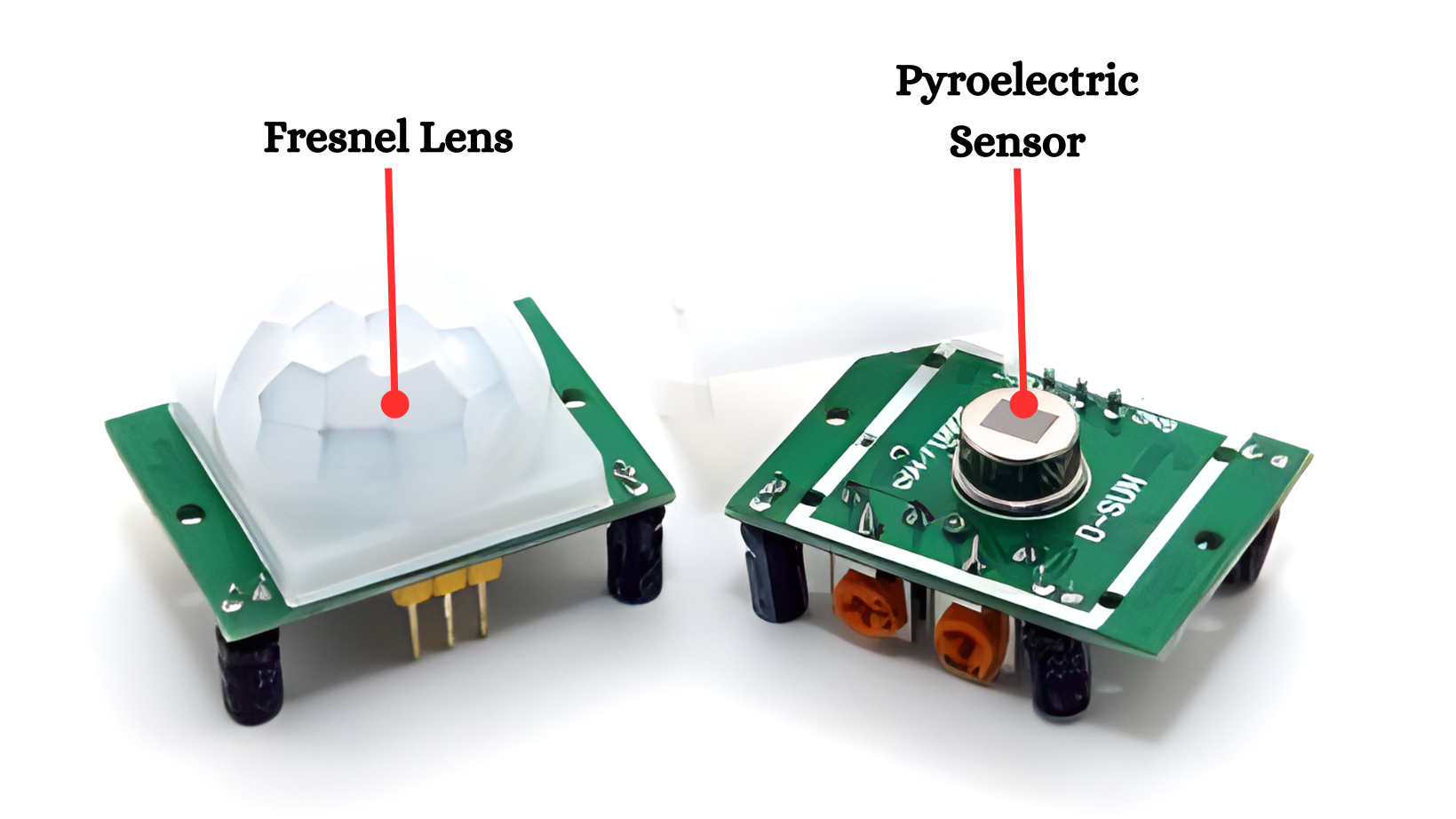
Pyroelectric Sensor:
- The core component that detects infrared radiation from moving objects, such as humans and animals. It has two balanced sensors that cancel each other out in the absence of motion.
Fresnel Lens:
- A plastic lens that focuses the infrared signals onto the PIR sensor element. It increases the detection area and improves the sensitivity of the sensor.
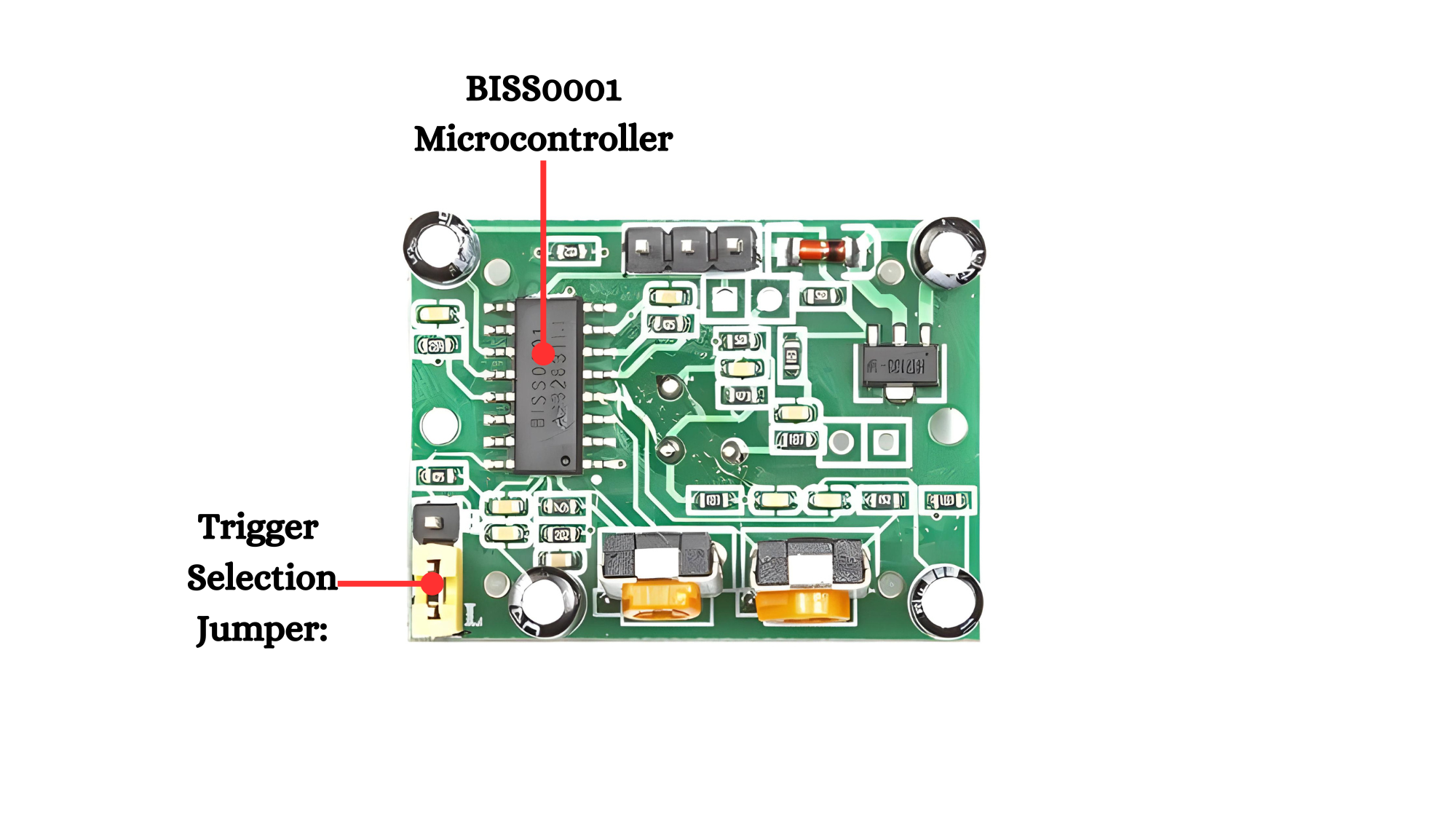
BISS0001 Microcontroller:
- A specialized integrated circuit (IC) that processes the signals from the PIR sensor element. It handles the detection logic and provides the output signal.
Trigger Selection Jumper:
- A jumper that allows you to select the trigger mode:
- H (retriggerable mode): The output will stay HIGH as long as motion is detected within the delay time.
- L (non-retriggerable mode): The output will go LOW after the delay time, even if motion is still detected.
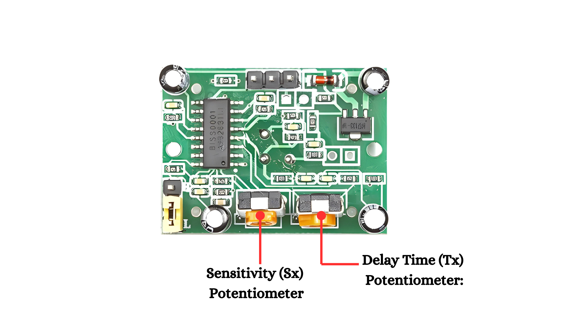
Adjustable Sensitivity (Sx) Potentiometer:
- A small variable resistor that allows you to adjust the sensitivity of the sensor. Turning it clockwise increases sensitivity, making the sensor detect smaller movements over a larger area.
Adjustable Delay Time (Tx) Potentiometer:
- Another variable resistor that lets you adjust the time delay for how long the output signal stays HIGH after motion is detected. The delay can be set from a few seconds to several minutes.
Working Principle
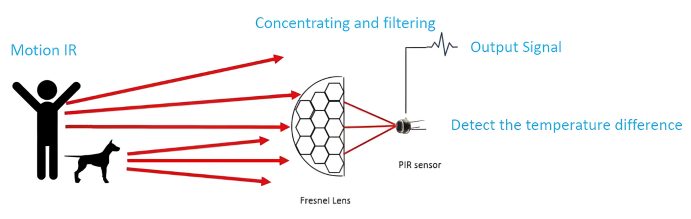
The Human body temperature will infraded with a wavelenght of 10um. The infrared are enhanced by a fresnel filter and concentrated on the pir sensor. When the pyroelectric element receives the infrared temperature change of the human body it will lose the electric charge balance and release the electric charge subsequent circuits can generate the signal after detection the charge.
Applications
- Security Systems: Detects movement to trigger alarms or lights for home and office security.
- Home Automation: Controls lights and devices based on occupancy, enhancing energy efficiency.
- Interactive Displays: Activates content or interactive elements when users approach.
- Industrial Monitoring: Monitors occupancy in industrial settings to optimize operations.
- Wildlife Cameras: Captures photos or videos of animals based on detected motion.
Technical Specifications
Here are the technical specifications for the HC-SR501 PIR sensor module:
- Operating voltage: DC 4.5V to 20V
- Quiescent current: < 50uA
- Level output voltage: High 3.3V / Low 0V.
- Trigger: Repeatable trigger (default) / Latching trigger (optional)
- Delay time: Adjustable (0.3 seconds to 300 seconds)
- Blocking time: 2.5 seconds (default)
- Detection range: Less than 120 degrees, up to 7 meters
- Operating temperature: -15 to 70 degrees Celsius
- Dimensions: 32mm x 24mm x 25mm
Pinout
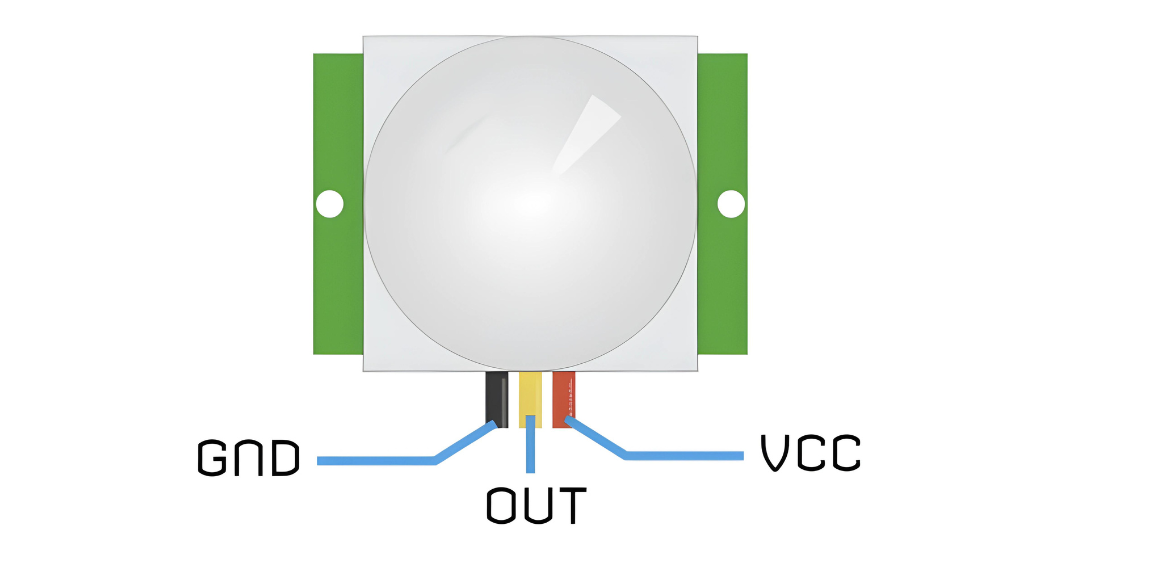
The HC-SR501 module has a 3-pin connector with a pinout as follows:
- VCC: This pin is the power supply for the sensor. It accepts input voltages between 5 to 12V, although 5V is commonly used.
- OUT: This pin is the 3.3V TTL logic output. It goes HIGH when motion is detected and LOW when idle (no motion detected).
- GND: This pin is the ground pin and should be connected to the ground of the power supply.
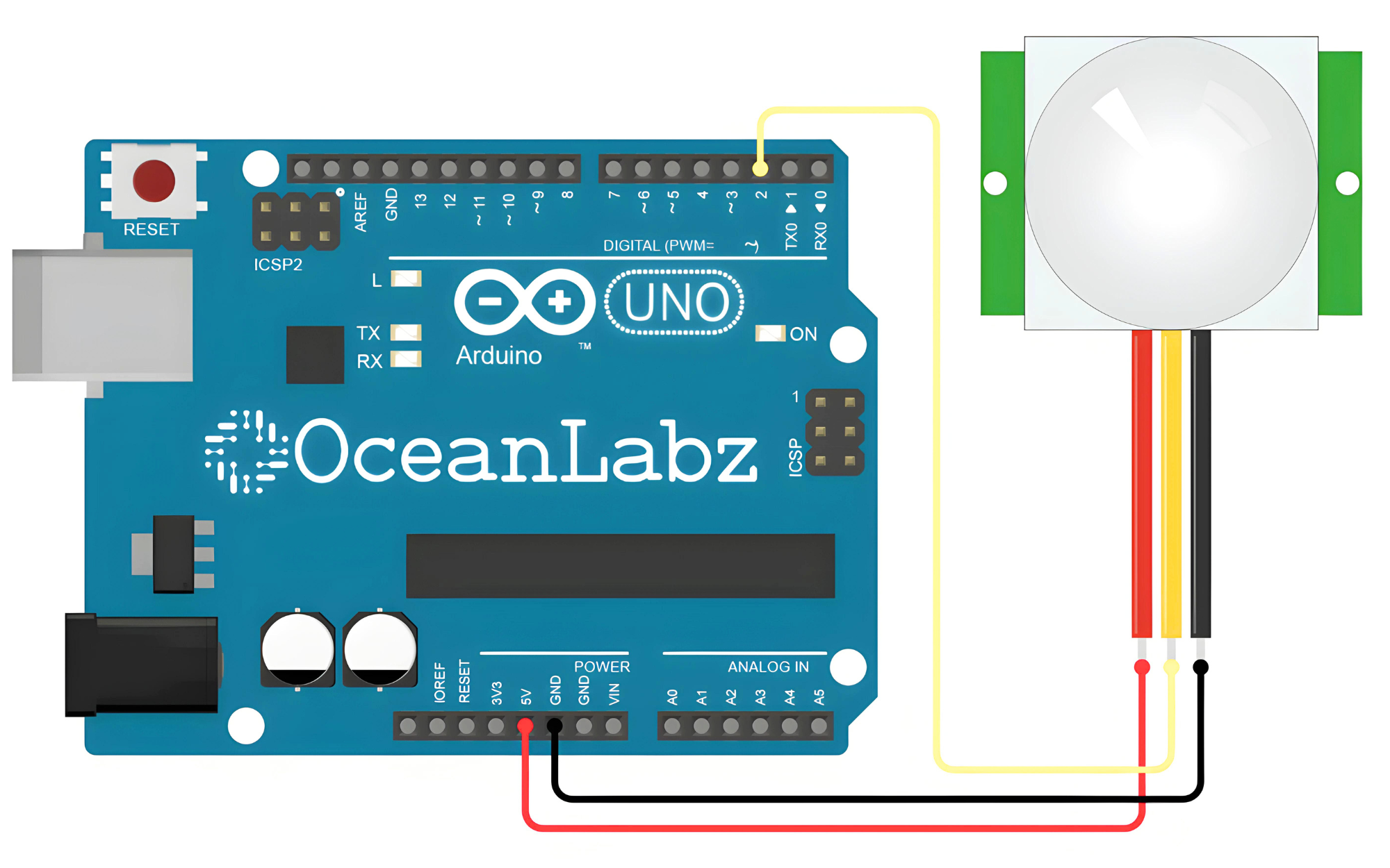
Circuit Diagram
| HC-SR501 PIR Pin | Arduino Pin |
| VCC | 5 V |
| GND | GND |
| OUT | D2 |
Programming With Arduino
Step 1: Open your first sketch
- Open the Arduino IDE.
- Copy and paste the provided code into a new sketch in the Arduino IDE:
#define PIR_Pin 2
#define LED 13
void setup() {
Serial.begin(9600);
pinMode(13, OUTPUT);
pinMode(2, INPUT);
}
void loop() {
int val = digitalRead(2);
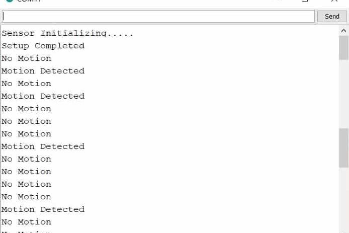
if (val == HIGH) {
Serial.println("Motion Detected");
digitalWrite(13, HIGH);
} else {
Serial.println("No motion detected.");
digitalWrite(13, LOW);
}
delay(1000);
}
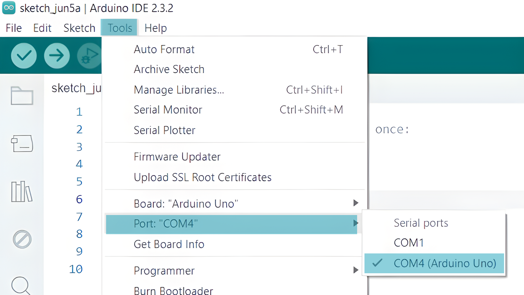
Step 2: Select your board type and port
You’ll need to select the entry in the Tools > Board menu that corresponds to your Arduino board.

Select the serial device of the board from the Tools | Serial Port menu. This is likely to be COM4 or higher (COM1 and COM2 are usually reserved for hardware serial ports). To find out, you can disconnect your board and re-open the menu; the entry that disappears should be the Arduino board. Reconnect the board and select that serial port.
Step 3: Upload the Sketch
- Click the “Upload” button (right arrow icon) to upload the sketch to the Arduino.

Step 3: Open the Serial Monitor:
- Go to Tools > Serial Monitor or press Ctrl+Shift+M to open the Serial Monitor.
- Ensure the baud rate in the Serial Monitor is set to 9600.