Index
Introduction
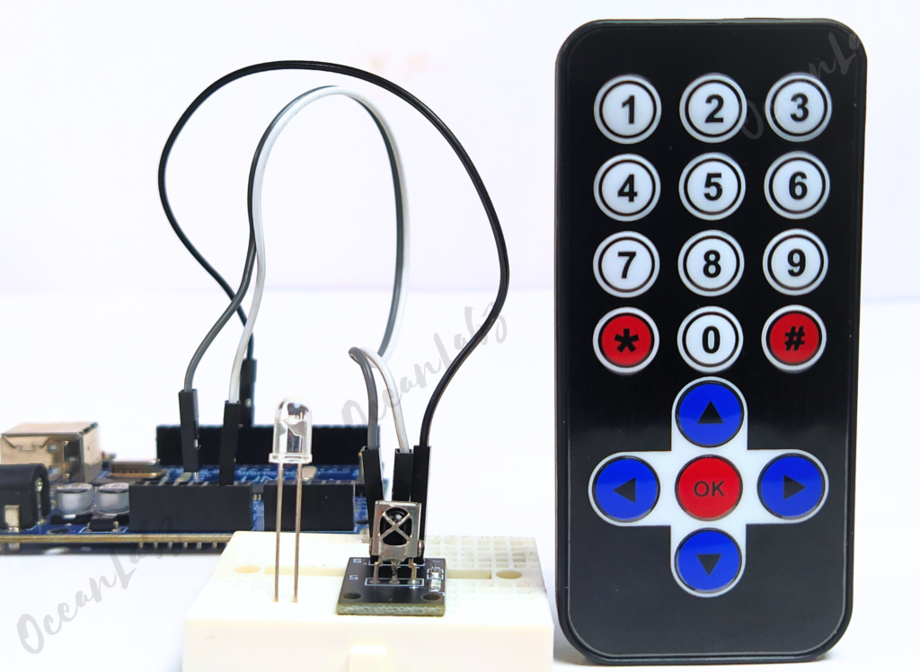
Infrared (IR) remotes are commonly used to control electronic devices. They work by emitting infrared light signals that are decoded by an IR receiver. In this tutorial, you will learn how to interface an IR remote with an Arduino, read button presses, and use them to control an LED.
Required Components
- Arduino UNO R3 SMD
- IR remote control
- IR receiver module
- 220-ohm resistor
- Breadboard
- Jumper wires
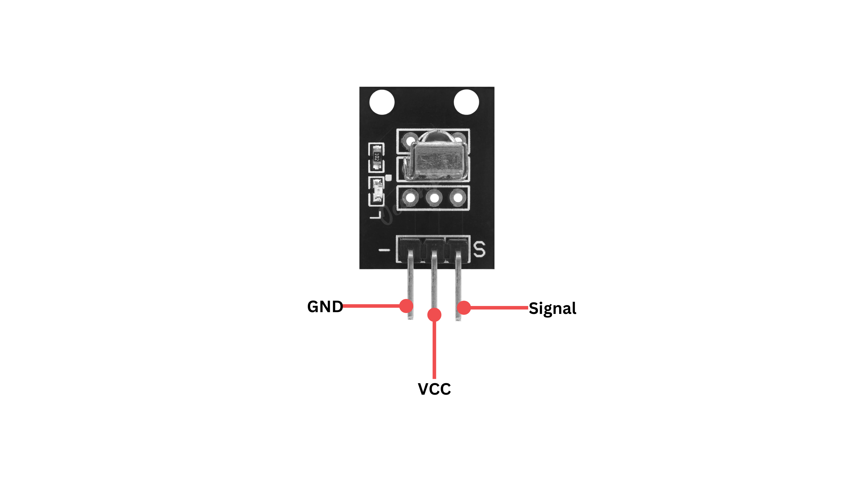
Pinout
Circuit Diagram / Wiring
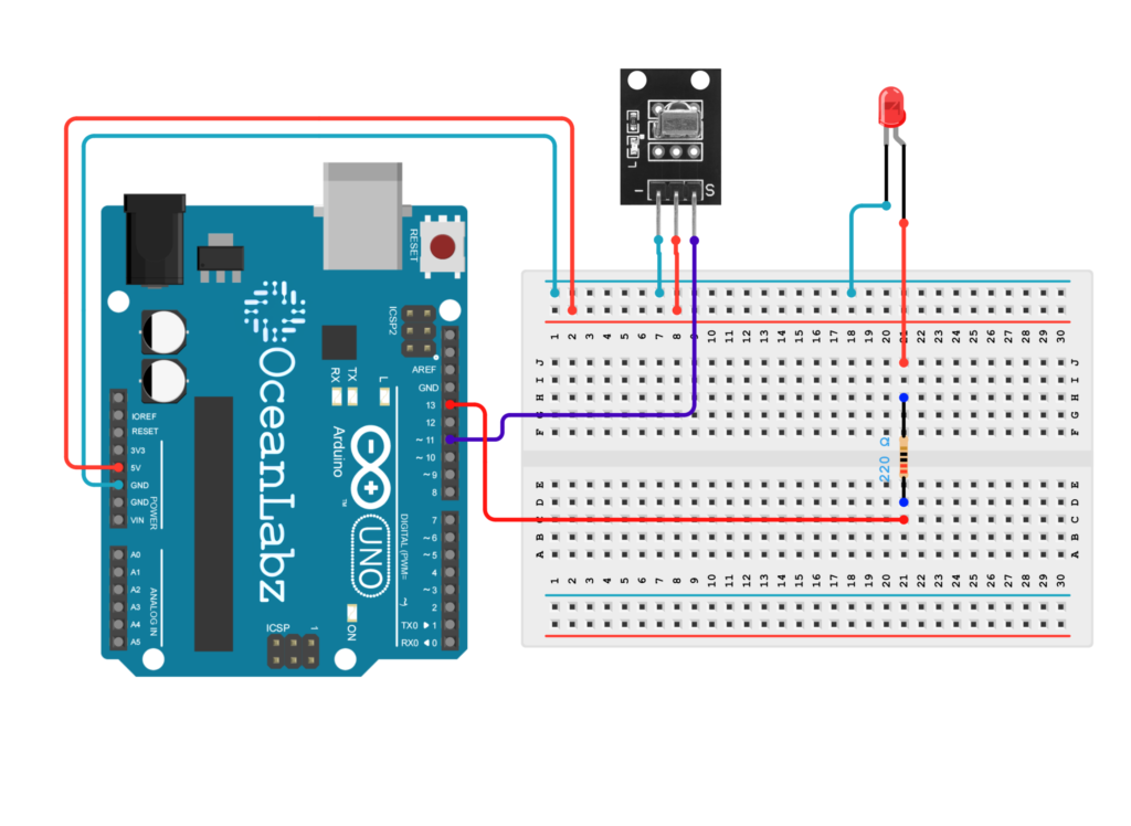
- IR Receiver:
- Connect the signal pin of the IR receiver to Arduino digital pin 11.
- Connect the VCC pin to the 5V pin on the Arduino.
- Connect the GND pin to the GND pin on the Arduino.
- LED:
- Connect the longer leg (anode) of the LED to digital pin 13 through a 220-ohm resistor.
- Connect the shorter leg (cathode) to the GND pin.
Arduino Code / Programming
- Go to the “Libraries” tab on the left-hand side of the screen.
- Click on the “Library Manager” button (book icon) at the top of the Libraries tab.
- In the Library Manager window, type “IRremote” in the search bar.
- Locate the “IRremote” library by shirriff and click on the “Install” button next to it.
- Wait for the library to be installed, and you’re ready to use the IRremote library in your projects.
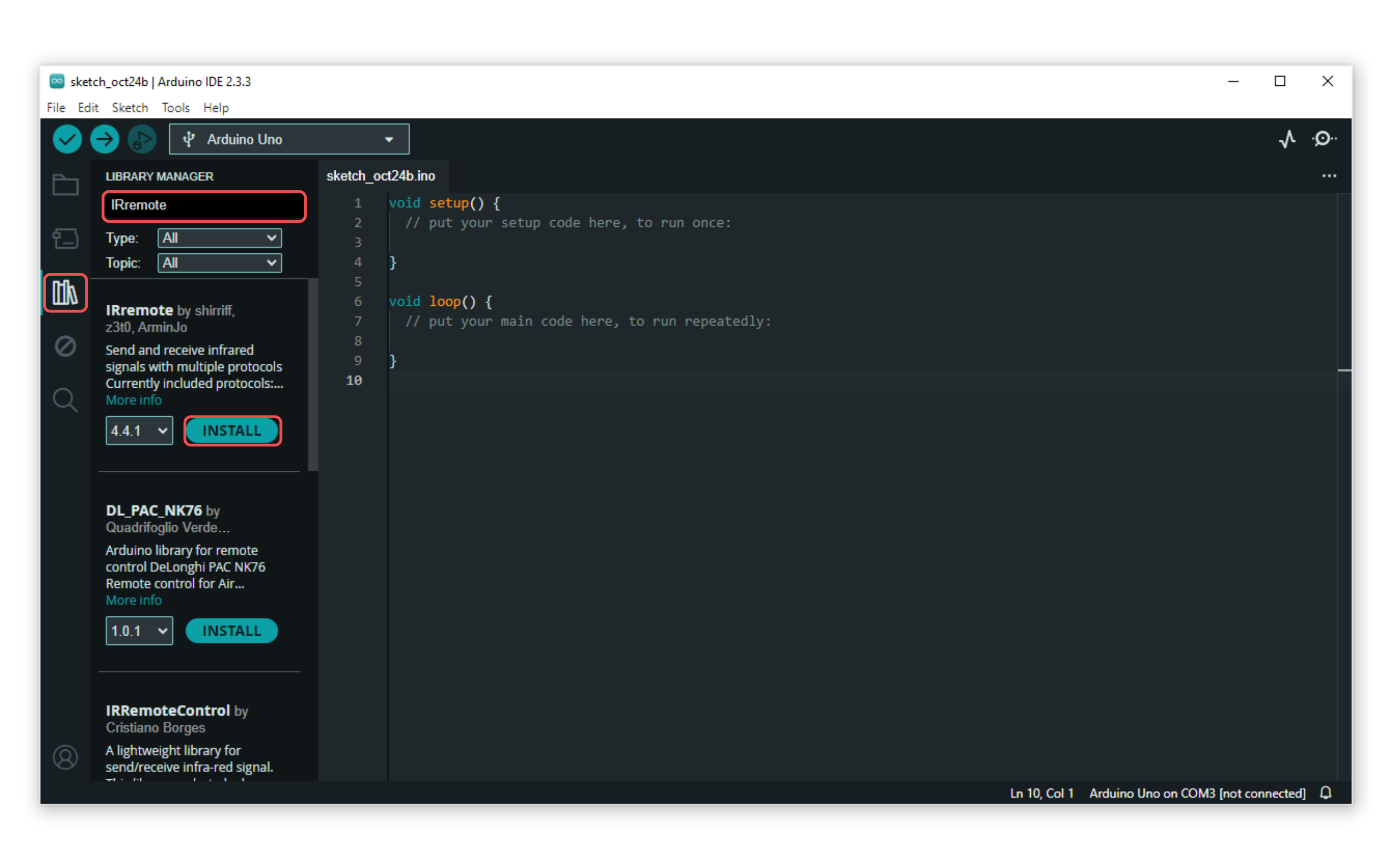
- Here’s a basic code example to read IR remote signals and control an LED:
#include <IRremote.h>  // Include the IRremote library

const int RECV_PIN = 11;  // Pin connected to the IR receiver
const int LED_PIN = 13;   // Pin connected to the LED

IRrecv irrecv(RECV_PIN);   // Create an instance of the IR receiver
decode_results results;     // Variable to store the results

// Define the button values for turning the LED on and off
const unsigned long ON_BUTTON_VALUE = 16753245; // Button value to turn LED on
const unsigned long OFF_BUTTON_VALUE = 16736925; // Button value to turn LED off

void setup() {
  Serial.begin(9600);         // Initialize serial communication
  irrecv.enableIRIn();        // Start the receiver
  pinMode(LED_PIN, OUTPUT);   // Set LED_PIN as an output
  digitalWrite(LED_PIN, LOW); // Ensure the LED is initially off
}

void loop() {
  if (irrecv.decode(&results)) {
    // Ignore the repeat code
    if (results.value == 4294967295) {
      irrecv.resume(); // Resume for the next value
      return; // Skip further processing for this loop iteration
    }

    // Print the received value for debugging
    Serial.print("Received value: ");
    Serial.println(results.value, DEC); // Print the value in decimal

    // Check if the received value matches the ON button value
    if (results.value == ON_BUTTON_VALUE) {
      digitalWrite(LED_PIN, HIGH); // Turn the LED on
      Serial.println("LED ON"); // Print message to Serial Monitor
    }
    // Check if the received value matches the OFF button value
    else if (results.value == OFF_BUTTON_VALUE) {
      digitalWrite(LED_PIN, LOW); // Turn the LED off
      Serial.println("LED OFF"); // Print message to Serial Monitor
    }

    irrecv.resume(); // Receive the next value
  }
}
Explanation of the Code
Library Inclusion:
#include <IRremote.h> // Include the IRremote library
- This line includes the
IRremotelibrary, which provides functions for receiving and decoding signals from IR remote controls.
Pin Definitions:
const int RECV_PIN = 11;  // Pin connected to the IR receiver
const int LED_PIN = 13;   // Pin connected to the LED
RECV_PINis the pin number where the IR receiver is connected to the Arduino.LED_PINis the pin number where the LED is connected.
IR Receiver Initialization:
IRrecv irrecv(RECV_PIN);   // Create an instance of the IR receiver
decode_results results;     // Variable to store the results
- An instance of
IRrecvis created to handle the IR receiver. decode_resultsis a structure that stores the decoded IR signals.
Button Value Definitions:
const unsigned long ON_BUTTON_VALUE = 16753245; // Button value to turn LED on
const unsigned long OFF_BUTTON_VALUE = 16736925; // Button value to turn LED off
ON_BUTTON_VALUEandOFF_BUTTON_VALUEare constants that represent the values transmitted by the remote control for turning the LED on and off, respectively.- You need to replace these values with the actual values received from your remote.
Setup Function:
void setup() {
  Serial.begin(9600);         // Initialize serial communication
  irrecv.enableIRIn();        // Start the receiver
  pinMode(LED_PIN, OUTPUT);   // Set LED_PIN as an output
  digitalWrite(LED_PIN, LOW); // Ensure the LED is initially off
}
- Initializes serial communication for debugging and monitoring.
- Starts the IR receiver to begin listening for signals.
- Sets
LED_PINas an output pin to control the LED. - Ensures the LED is off when the program starts.
Loop Function:
void loop() {
  if (irrecv.decode(&results)) {
    // Ignore the repeat code
    if (results.value == 4294967295) {
      irrecv.resume(); // Resume for the next value
      return; // Skip further processing for this loop iteration
    }
- The
loop()function continuously checks for incoming IR signals. - If a signal is detected, it decodes it and stores the result in the
resultsvariable. - The code checks if the received value is
4294967295, which indicates a repeat signal. If it is, the code resumes listening for the next signal and skips the rest of the loop.
Processing Received Values:
    // Print the received value for debugging
    Serial.print("Received value: ");
    Serial.println(results.value, DEC); // Print the value in decimal

    // Check if the received value matches the ON button value
    if (results.value == ON_BUTTON_VALUE) {
      digitalWrite(LED_PIN, HIGH); // Turn the LED on
      Serial.println("LED ON"); // Print message to Serial Monitor
    }
    // Check if the received value matches the OFF button value
    else if (results.value == OFF_BUTTON_VALUE) {
      digitalWrite(LED_PIN, LOW); // Turn the LED off
      Serial.println("LED OFF"); // Print message to Serial Monitor
    }

    irrecv.resume(); // Receive the next value
  }
}
- The received value is printed to the Serial Monitor for debugging purposes.
- The code checks if the received value matches the predefined
ON_BUTTON_VALUE. If it does, the LED is turned on, and a message is printed. - Similarly, if the received value matches
OFF_BUTTON_VALUE, the LED is turned off, and a message is printed. - Finally,
irrecv.resume()is called to continue listening for the next IR signal.
Troubleshooting
- Ensure the IRremote library is installed and compatible with your Arduino IDE version.
- Verify the IR receiver is connected to the correct pin (RECV_PIN = 11) and has proper power and ground connections.
- Check the ON_BUTTON_VALUE and OFF_BUTTON_VALUE by printing the actual received values to match your remote’s codes.
- Ensure the LED is properly connected to pin 13, with a current-limiting resistor, and test it separately if needed.
Arduino projects:
Arduino project 1 – IR Remote Code Lock with Timer
This Arduino project uses an IR remote control to unlock an LED by pressing a specific sequence of buttons. The sequence consists of three predefined IR codes, and the LED will turn on once the correct sequence is completed. If the wrong button is pressed or no input is received within 5 seconds, the sequence resets. The project also allows for manual resetting of the sequence through the Serial Monitor, providing an interactive and controlled way to unlock the LED using an IR remote.
Arduino Code / Programming
#include <IRremote.h>

const int receiverPin = 11;
const int ledPin = 13;
unsigned long lastButtonPress = 0;
int currentStep = 0;

const unsigned long timeout = 5000;  // 5 seconds to enter code
unsigned long sequence[] = {0xFFA25D, 0xFF629D, 0xFFE21D};  // Example: Button 1, Button 2, Button 3

IRrecv irrecv(receiverPin);
decode_results results;

void setup() {
  pinMode(ledPin, OUTPUT);
  digitalWrite(ledPin, LOW);
  irrecv.enableIRIn();
  Serial.begin(9600);  // Initialize Serial Monitor
}

void loop() {
  if (irrecv.decode(&results)) {
    unsigned long code = results.value;
    lastButtonPress = millis();

    // Print the received code to the Serial Monitor
    Serial.print("Received code: ");
    Serial.println(code, HEX);


  if (code == 0xFFFFFFFF) {
  irrecv.resume(); // Skip this invalid code
  return;
}

    // Check if current code matches sequence step
    if (code == sequence[currentStep]) {
      Serial.print("Correct code for step ");
      Serial.println(currentStep + 1);
      currentStep++;
    } else {
      Serial.println("Incorrect code, resetting sequence.");
      currentStep = 0;  // Reset if wrong code
    }

    // If the sequence is completed
    if (currentStep == 3) {
      Serial.println("Sequence complete! LED unlocked.");
      digitalWrite(ledPin, HIGH);  // Unlock by turning on LED
      currentStep = 0;             // Reset to start over
    }

    irrecv.resume();  // Receive next value
  }

  // Check for timeout
  if (millis() - lastButtonPress > timeout) {
    Serial.println("Timeout reached, resetting sequence.");
    currentStep = 0;  // Reset the sequence on timeout
    digitalWrite(ledPin, LOW);  // Turn off LED if not unlocked
  }

  // Serial command to reset sequence manually
  if (Serial.available()) {
    char input = Serial.read();
    if (input == 'r' || input == 'R') {
      Serial.println("Manual reset triggered.");
      currentStep = 0;
      digitalWrite(ledPin, LOW);
    }
  }
}
Explanation
- IR Remote Control: The code uses an IR remote to control an LED by pressing a sequence of three buttons.
- Button Sequence: The LED lights up when the correct sequence of button presses is received.
- Timeout and Reset: If no input is received within 5 seconds or an incorrect button is pressed, the sequence resets.
- Manual Reset: The sequence can be reset manually via the Serial Monitor by typing ‘r’ or ‘R’.
Arduino project 2 – Random Pattern Generation with IR Control
This Arduino project uses an IR remote control to generate and play a random LED blinking pattern. When Button 4 on the remote is pressed, a random sequence of on/off durations is created, and the LED blinks accordingly. The random pattern consists of five random delay times, ranging from 100ms to 1000ms, to create a dynamic and unpredictable LED light show. This project showcases the use of an IR remote, random number generation, and LED control to create engaging light patterns.
Arduino Code / Programming
#include <IRremote.h>

const int receiverPin = 11;
const int ledPin = 13;
int pattern[5];  // Array to store random pattern
bool patternGenerated = false;

IRrecv irrecv(receiverPin);
decode_results results;

void setup() {
  pinMode(ledPin, OUTPUT);
  irrecv.enableIRIn();
  randomSeed(analogRead(0));  // Use noise to seed random generator
}

void loop() {
  if (irrecv.decode(&results)) {
    unsigned long code = results.value;

    // Generate a random pattern on Button 4 press
    if (code == 0xFF10EF) {  // Replace with your code for Button 4
      generateRandomPattern();
      patternGenerated = true;
    }

    irrecv.resume();  // Receive next value
  }

  if (patternGenerated) {
    playPattern();  // Play the generated pattern
  }
}

void generateRandomPattern() {
  for (int i = 0; i < 5; i++) {
    pattern[i] = random(100, 1000);  // Random delay between 100 and 1000ms
  }
}

void playPattern() {
  for (int i = 0; i < 5; i++) {
    digitalWrite(ledPin, HIGH);
    delay(pattern[i]);
    digitalWrite(ledPin, LOW);
    delay(pattern[i]);
  }
}
Explanation
- IR Remote Control: The LED pattern is controlled via an IR remote, with Button 4 triggering the pattern generation.
- Random Pattern: When Button 4 is pressed, a random pattern of on/off durations (between 100ms and 1000ms) is generated and stored in the
patternarray. - Pattern Playback: The generated pattern is played by blinking the LED according to the random delays in the
patternarray. - Seeding Random Generator: The
randomSeed(analogRead(0))uses analog noise as a seed for generating unpredictable random values.
Arduino project 3 – IR Remote-Controlled Brightness Adjustment
This Arduino project uses an IR remote control to adjust the brightness of an LED connected to PWM pin 9. By pressing the Volume Up and Volume Down buttons on the remote, the LED’s brightness increases or decreases in increments of 25. The brightness level is wrapped around, so it resets to the minimum or maximum value when it exceeds the allowable range. The project demonstrates basic IR communication and LED dimming using PWM on the Arduino.
Arduino Code / Programming
#include <IRremote.h>

const int receiverPin = 11;   // Pin for IR receiver
const int ledPin = 9;         // PWM pin for LED
int brightness = 128;         // Starting brightness level

IRrecv irrecv(receiverPin);   // Create IR receiver object
decode_results results;       // Variable to store IR codes

void setup() {
  pinMode(ledPin, OUTPUT);
  irrecv.enableIRIn();        // Start the receiver
}

void loop() {
  if (irrecv.decode(&results)) {
    unsigned long code = results.value;

    // Volume Up button to increase brightness
    if (code == 0xFF629D) { // Replace with your own code for Volume Up
      brightness += 25;
      if (brightness > 255) {
        brightness = 0;      // Reset if it exceeds max brightness
      }
    }

    // Volume Down button to decrease brightness
    if (code == 0xFFA857) { // Replace with your own code for Volume Down
      brightness -= 25;
      if (brightness < 0) {
        brightness = 255;    // Reset if it goes below minimum
      }
    }

    analogWrite(ledPin, brightness); // Adjust LED brightness
    irrecv.resume();                  // Receive the next value
  }
}
Explanation
- The IR receiver listens for specific button presses from an IR remote control.
- The Volume Up button (
0xFF629D) increases the LED brightness by 25, and if the brightness exceeds 255, it resets to 0. - The Volume Down button (
0xFFA857) decreases the brightness by 25, and if it goes below 0, it resets to 255. - The brightness is controlled using the
analogWritefunction, allowing the LED connected to pin 9 to change brightness based on the button pressed.
Testing and Troubleshooting
- Open the Serial Monitor to see the hexadecimal values printed when you press buttons on the IR remote.
- Replace the hexadecimal values in the code with the values corresponding to your remote’s buttons.
- If the receiver does not detect signals, ensure that the connections are correct and the IR receiver is not blocked.
Arduino Project 4 – IR-Controlled Secure Stepper Lock System
This project uses an IR remote to control a stepper motor. The motor remains locked until a specific sequence of IR codes is received. Upon correct code input, the motor is unlocked and rotates, with visual feedback provided by LEDs and a buzzer. Incorrect codes or timeouts trigger a reset. This system can be used for secure motor activation based on IR signals.
Required Components
- Arduino UNO R3 SMD
- IR remote control
- IR receiver module (e.g., TSOP1738)
- Stepper Motor(28YBJ-48), ULN2003 Driver
- LED
- 220-ohm resistor
- Buzzer Module
- Breadboard
- Jumper wires
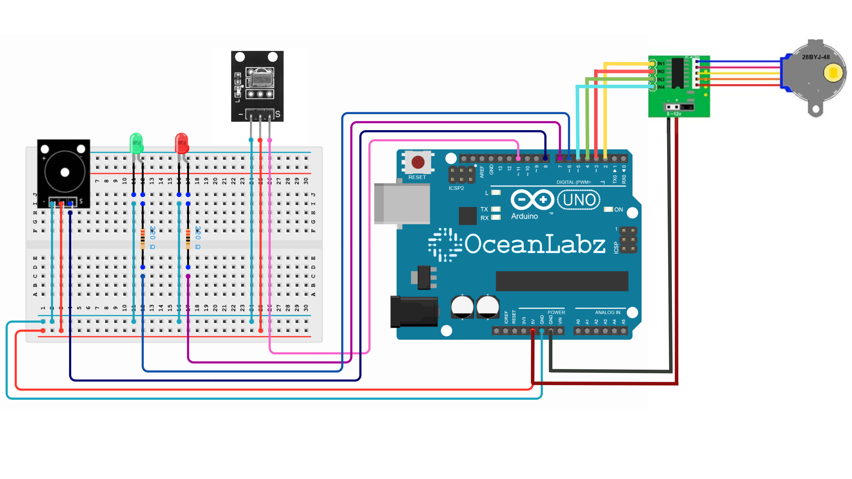
Circuit Diagram / Wiring
- ULN2003
- ULN2003 VCC → 5V (Arduino)
- ULN2003 GND → GND (Arduino)
- ULN2003 IN1 → Pin D2 (Arduino)
- ULN2003 IN2 → Pin D3 (Arduino)
- ULN2003 IN3 → Pin D4 (Arduino)
- ULN2003 IN4 → Pin D5 (Arduino)
- IR Receiver
- Receiver VCC → 5V (Arduino)
- Receiver GND → GND (Arduino)
- Receiver SIGNAL → Pin D11 (Arduino)
- Buzzer Module
- Buzzer VCC → 5V (Arduino)
- Buzzer GND → GND (Arduino)
- Buzzer SIGNAL → Pin D8 (Arduino)
- LEDs
- Connect the red LED anode to pin 7 (via a 220-ohm resistor) and cathode to GND.
- Connect the green LED anode to pin 6 (via a 220-ohm resistor) and cathode to GND.
Arduino Code
Make sure you have the required libraries installed:
- IRremote library for IR receiver.
- Stepper library for Stepper motor.
#include <IRremote.h>
#include <Stepper.h>

// Pin Configurations
const int receiverPin = 11;
const int greenLedPin = 6;
const int redLedPin = 7;
const int buzzerPin = 8;

// Stepper Motor Configuration
const int stepsPerRevolution = 2048; // Steps for 28BYJ-48 motor
const int stepperPin1 = 2;
const int stepperPin2 = 3;
const int stepperPin3 = 4;
const int stepperPin4 = 5;

unsigned long lastButtonPress = 0;
int currentStep = 0;
bool motorRunning = false;

// IR Sequence
const unsigned long timeout = 5000; // 5 seconds timeout
unsigned long sequence[] = {0xFFA25D, 0xFFE21D, 0xFF02FD};

// IR and Stepper Setup
IRrecv irrecv(receiverPin);
decode_results results;
Stepper myStepper(stepsPerRevolution, stepperPin1, stepperPin3, stepperPin2, stepperPin4);

void setup() {
  pinMode(greenLedPin, OUTPUT);
  pinMode(redLedPin, OUTPUT);
  pinMode(buzzerPin, OUTPUT);

  digitalWrite(greenLedPin, LOW);
  digitalWrite(redLedPin, LOW);

  irrecv.enableIRIn();  // Start receiving IR signals
  Serial.begin(9600);

  myStepper.setSpeed(10); // Adjust motor speed
  resetSystem();
}

void beep(int pin, int duration) {
  for (int i = 0; i < duration * 2; i++) { // 1 kHz tone
    digitalWrite(pin, LOW);
    delayMicroseconds(500);
    digitalWrite(pin, HIGH);
    delayMicroseconds(500);
  }
}

void moveStepper(int steps) {
  motorRunning = true;
  myStepper.step(steps);
  motorRunning = false;
}

void resetSystem() {
  currentStep = 0;
  digitalWrite(greenLedPin, LOW);
  digitalWrite(redLedPin, LOW);
  //moveStepper(-stepsPerRevolution); // Lock position
}

void loop() {
  // Check for IR signal reception, even if the motor is moving
  if (irrecv.decode(&results)) {
    unsigned long code = results.value;

    Serial.println(code);
    if (code == 0xFFFFFFFF) {
      irrecv.resume();
      return; // Ignore repeat codes
    }

    Serial.print("Received code: ");
    Serial.println(code, HEX);

    // Match the current sequence step
    if (code == sequence[currentStep]) {
      currentStep++;

      // beep(buzzerPin, 200);

      if (currentStep == 3) {
        Serial.println("Sequence complete! Stepper motor unlocked.");
        digitalWrite(greenLedPin, HIGH);
        digitalWrite(redLedPin, LOW);
        moveStepper(stepsPerRevolution); // Unlock position
        resetSystem();
      }
    } else {
      Serial.println("Incorrect code, resetting sequence.");
      digitalWrite(redLedPin, HIGH);
      beep(buzzerPin, 200);
      resetSystem();

    }

    lastButtonPress = millis(); // Update last button press time
    irrecv.resume();            // Resume IR reception
  }

  // Timeout Handling
  if (millis() - lastButtonPress > timeout) {
    if (currentStep > 0) {
      Serial.println("Timeout reached, resetting sequence.");
      resetSystem();
    }
  }

}
Explanation
- This project uses an IR remote to control a stepper motor and LEDs.
- A specific sequence of IR codes unlocks the motor, allowing it to rotate.
- When the correct sequence is received, the motor moves and the green LED lights up.
- If the wrong code is entered or timeout occurs, the system resets with a red LED and a beep.
- The stepper motor remains locked until the correct code sequence is received.

