Index
Introduction
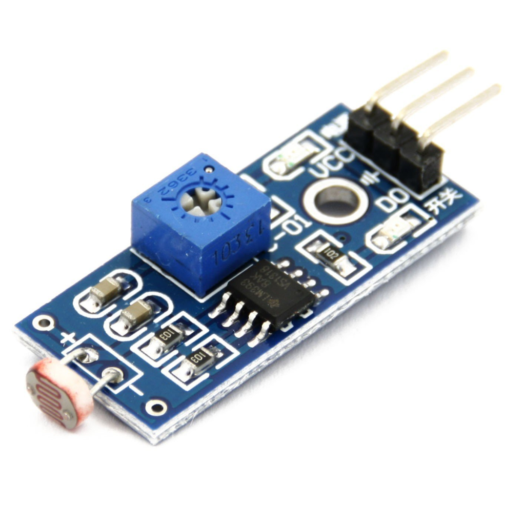
LDR (Light Dependent Resistor) Sensor Module, also known as a photoresistor module, is a type of sensor designed to detect and measure the intensity of light in its surrounding environment. LDRs are passive components whose resistance changes in response to varying light levels. When integrated into a sensor module, LDRs provide a convenient way to detect light for various applications.
Hardware Overview
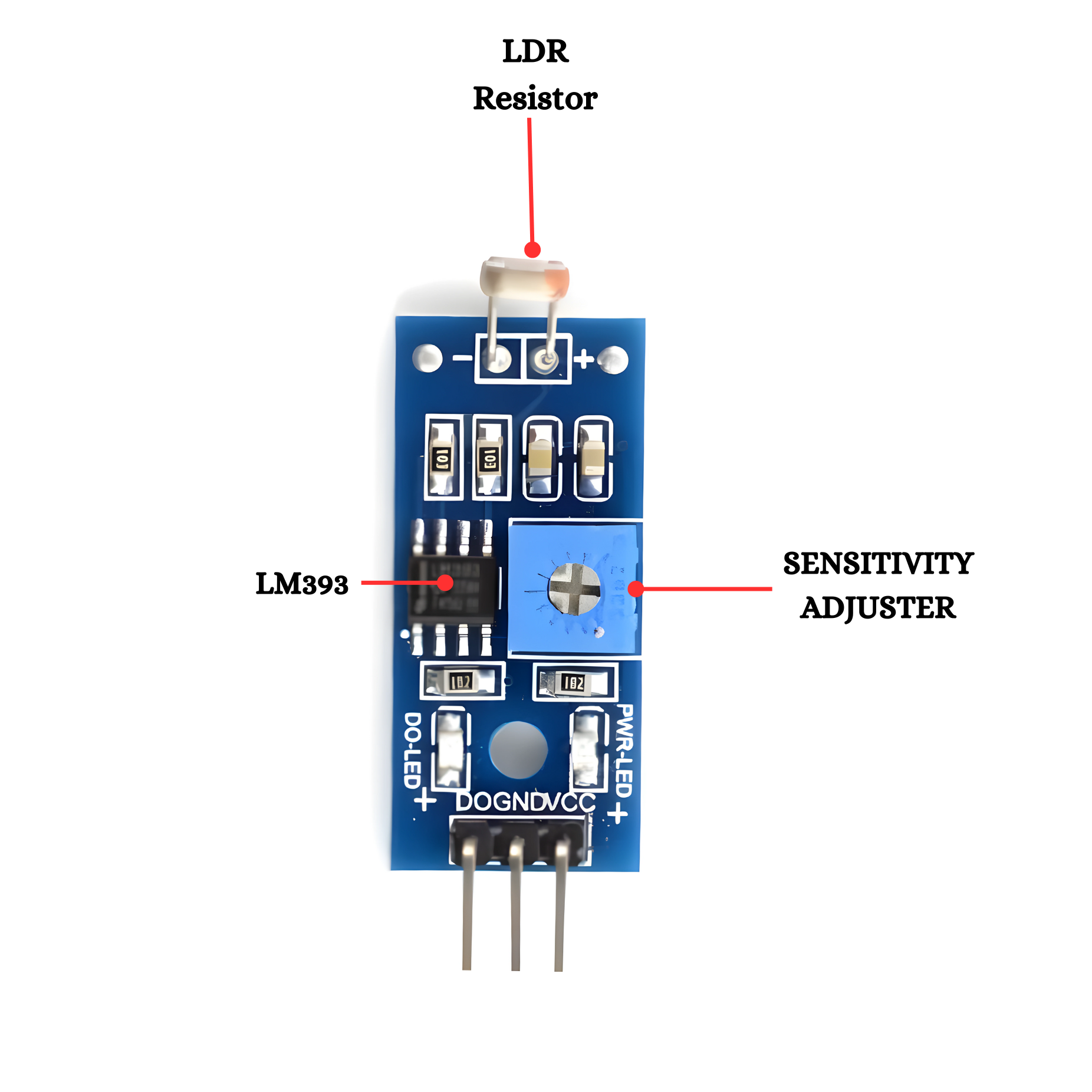
LDR Resistor: The Light Dependent Resistor (LDR), often made from cadmium sulfide (CdS), changes its resistance based on the intensity of light it is exposed to. In darkness, its resistance is high, and in bright light, it is low. This property makes it useful for detecting light levels in various applications, such as automatic lighting systems and light meters. The LDR’s resistance decrease with increasing light intensity, allowing it to function as a sensor for light changes. It is commonly used in circuits where the presence or intensity of light needs to be monitored.
LM393: The LM393 is a dual comparator IC that is used for comparing two voltage levels and outputting a high or low signal based on the comparison. It contains two independent voltage comparators, each with an open-collector output. The LM393 is commonly used in applications such as voltage level detection, pulse-width modulation, and light sensors. It operates with a wide supply voltage range and can interface with a variety of analog signals. The IC is widely used in simple circuits for applications like zero-crossing detectors, voltage level indicators, and as part of various sensor systems.
Sensitivity Adjuster: The sensitivity adjuster, usually a potentiometer, allows users to fine-tune the LDR sensor’s response to light intensity. By turning the potentiometer, you can increase or decrease the threshold at which the sensor detects changes in light, making it more or less sensitive to ambient light levels.
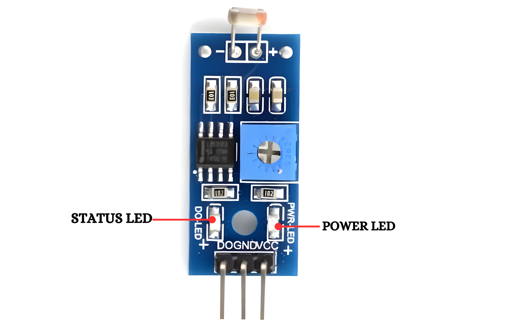
Status LED: The status LED provides a visual indicator of the sensor’s operational state. It typically lights up when the sensor detects light or when power is supplied to the module. This LED helps in troubleshooting and confirms that the sensor is functioning correctly.
Power LED: The power LED indicates that the sensor module is receiving power. It lights up when the module is connected to a power source, confirming that the circuit is active and operational.
Working Principle
LDRs are tiny light-sensing devices also known as photoresistors. An LDR is a resistor whose resistance changes as the amount of light falling on it changes. The resistance of the LDR decreases with an increase in light intensity. This property allows us to use them for making light sensing circuits.
Application
- Automatic Lighting Systems: Adjusting brightness based on ambient light levels.
- Brightness Measurement Devices: Controlling display brightness and backlight intensity.
- Solar Tracking Systems: Optimizing solar panel orientation for maximum energy harvesting.
- Security Systems: Detecting movement or intrusion by changes in light levels.
- DIY Electronics Projects: Used in hobbyist and educational setups for light-sensitive circuits.
- Environmental Monitoring: Measuring ambient light levels for analyzing environmental conditions.
- Darkness Detection: Activating devices based on light presence or absence.
- Energy Management: Optimizing energy consumption based on natural light availability.
Technical Specifications
- LM393 based design.
- Operating Voltage: 3.3V to 5V DC.
- Operating Current: 15ma.
- Can detect ambient brightness and light intensity.
- Adjustable sensitivity (via blue digital potentiometer adjustment).
- Output Digital – 0V to 5V, Adjustable trigger level from preset.
- LEDs indicating output and power.
Pinout
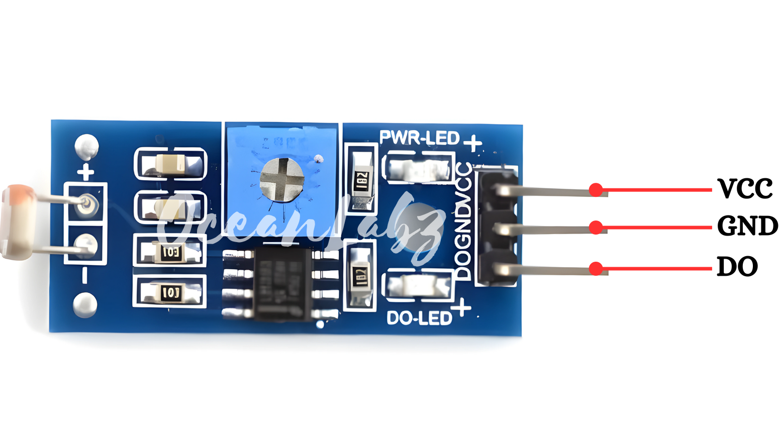
- VCC: This pin connects to a positive voltage supply (e.g., 5V or 3.3V) to power the sensor module.
- GND: This pin is connected to the ground (0V) of the power supply.
- OUT: This pin outputs an analog or digital signal that varies with the detected light level.
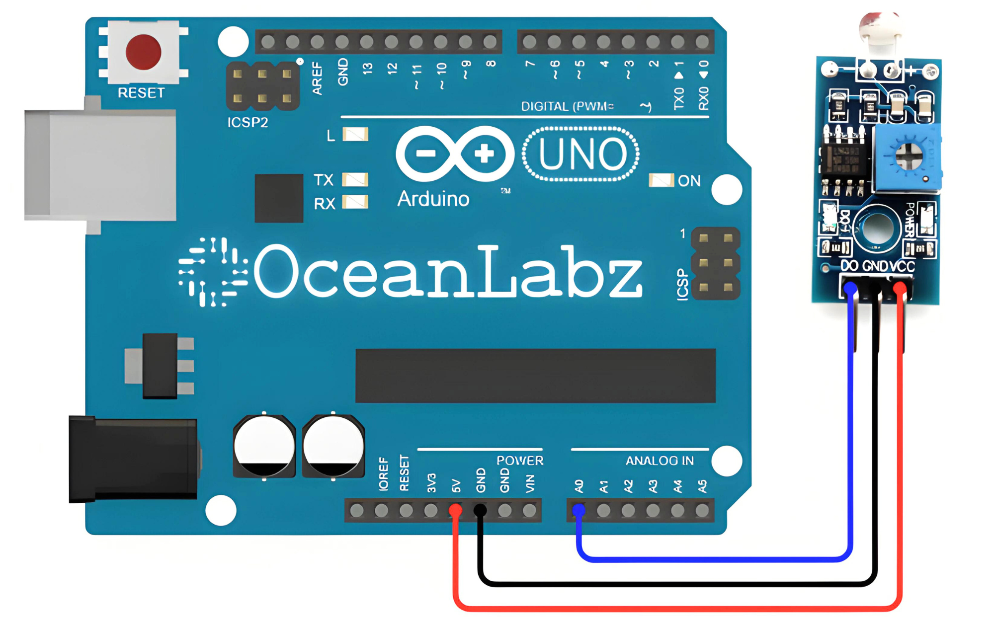
Circuit Diagram
| LDR Pin | Arduino Pin |
| VCC | 3 V |
| GND | GND |
| OUT | Analoge A0 |
Programming With Arduino
Step 1: Open your first sketch
- Open the Arduino IDE.
- Copy and paste the provided code into a new sketch in the Arduino IDE:
// Define LDR sensor pin
const int ldrPin = A0;  // Analog input pin connected to LDR sensor

void setup() {
  Serial.begin(9600);  // Initialize serial communication
}

void loop() {
  // Read analog value from LDR sensor
  int sensorValue = analogRead(ldrPin);

  // Print the raw sensor value to serial monitor
  Serial.print("LDR Sensor Value: ");
  Serial.println(sensorValue);

  // Add a delay to reduce the rate of readings (optional)
  delay(1000);  // Delay for 1 second before next reading
}
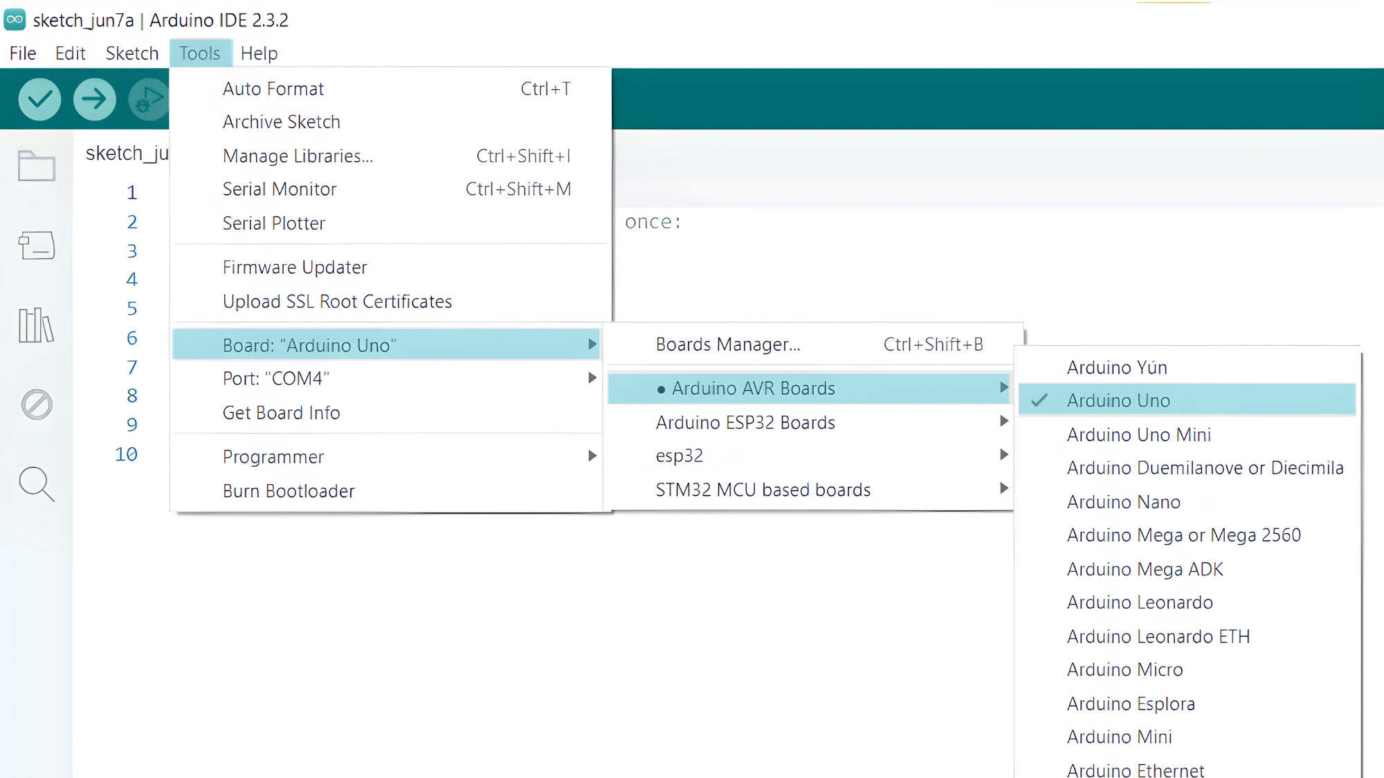
Step 2: Select your board type and port
- Go to Tools > Board and select your Arduino board (e.g., Arduino Uno).
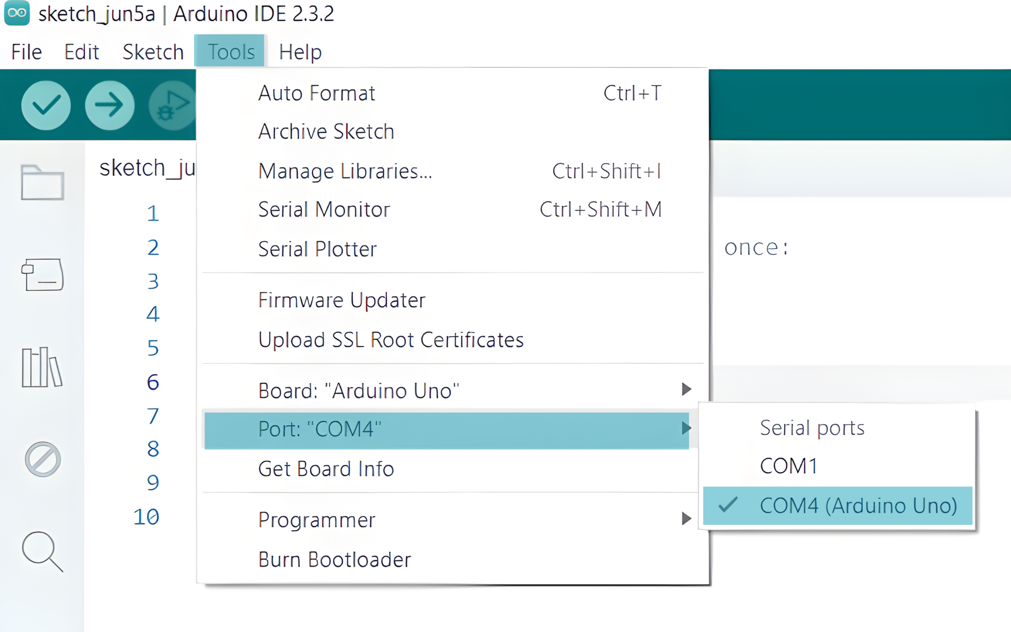
- Go to Tools > Port and select the port to which your Arduino is connected.
- Verify and upload the code to your Arduino board.
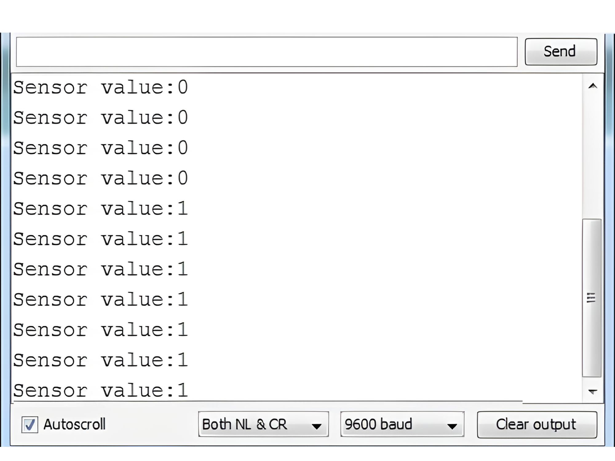
Step 3: Open Serial Monitor:
- Once the code is uploaded successfully, open the Serial Monitor in the Arduino IDE.
- Set the baud rate to 9600 baud.