Index

Introduction
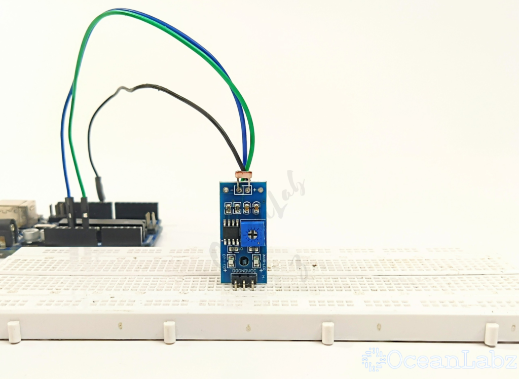
An LDR (Light Dependent Resistor), also known as a photoresistor, changes its resistance based on the amount of light that hits it. This tutorial will guide you through using an LDR sensor module with Arduino to detect light levels.
Required Components
- Arduino board (e.g., Uno, Nano)
- LDR sensor module
- LED
- Jumper wires
- Breadboard (optional)
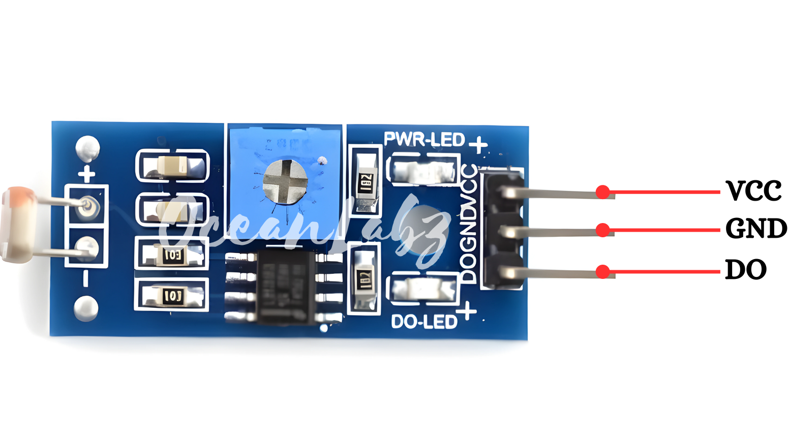
Pinout

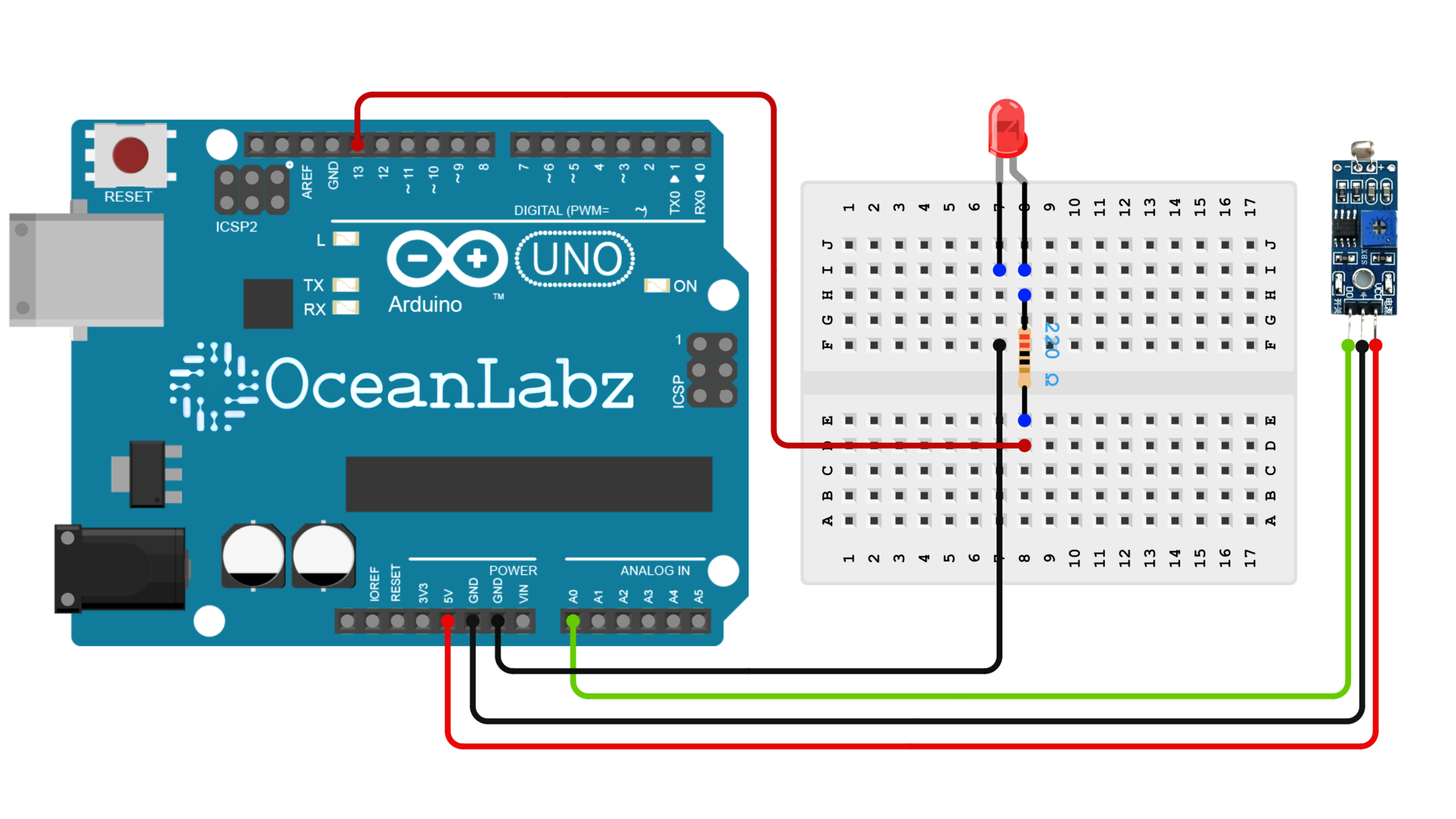
Circuit Diagram / Wiring
- LDR Sensor module
- LDR VCC → 5V (Arduino)
- LDR GND → GND (Arduino)
- LDR DO → Pin A0 (Arduino)
- LED
- Connect the longer leg (anode) of the LED to digital pin 13 through a 220-ohm resistor.
- Connect the shorter leg (cathode) to the GND pin.

Programming With Arduino
- Copy and paste the provided code into a new sketch in the Arduino IDE:
// Define LDR sensor and LED pin
const int ldrPin = A0;  // Analog input pin connected to LDR sensor
const int ledPin = 13;  // Digital output pin connected to LED

void setup() {
  Serial.begin(9600);      // Initialize serial communication
  pinMode(ledPin, OUTPUT); // Set LED pin as output
}

void loop() {
  // Read analog value from LDR sensor
  int sensorValue = analogRead(ldrPin);

  // Print a custom message to the serial monitor with the sensor value
  Serial.print("Current Light Intensity Level: ");
  Serial.println(sensorValue);

  // Set a threshold for LED to turn on/off based on light intensity
  int threshold = 500;

  if (sensorValue < threshold) {
    digitalWrite(ledPin, HIGH);  // Turn LED on if light level is low
    Serial.println("LED ON - It's dark!");
  } else {
    digitalWrite(ledPin, LOW);   // Turn LED off if light level is high
    Serial.println("LED OFF - It's bright!");
  }

  // Add a delay to reduce the rate of readings (optional)
  delay(1000);  // Delay for 1 second before next reading
}
Explanation:
- The
thresholdvariable sets the light level at which the LED turns on or off. You can adjust this depending on your environment or requirements. - When the light level (LDR value) is below the threshold (indicating darkness), the LED turns on, and the serial monitor shows a message saying “LED ON – It’s dark!”
- When the light level is above the threshold (indicating brightness), the LED turns off, and the serial monitor displays “LED OFF – It’s bright!”
Testing and Troubleshooting
- Verify Connections: Ensure that all components are connected correctly. Check that the LDR sensor is connected to the correct analog pin (A0) and the LED is on the designated digital pin (13).
- Threshold Adjustment: If the LED does not respond as expected, try adjusting the
thresholdvalue in the code to match your environment’s light levels. You may need a lower or higher value depending on ambient lighting.
- Serial Monitor Check: Open the Serial Monitor to verify that the LDR values are being read and printed. This will help confirm whether the sensor is functioning and whether values are reasonable based on the room’s light conditions.
- LED Troubleshooting: If the LED does not turn on, check its polarity. The longer leg should connect to the positive pin (digital pin 13), and the shorter leg should connect to ground.


