Index
Introduction
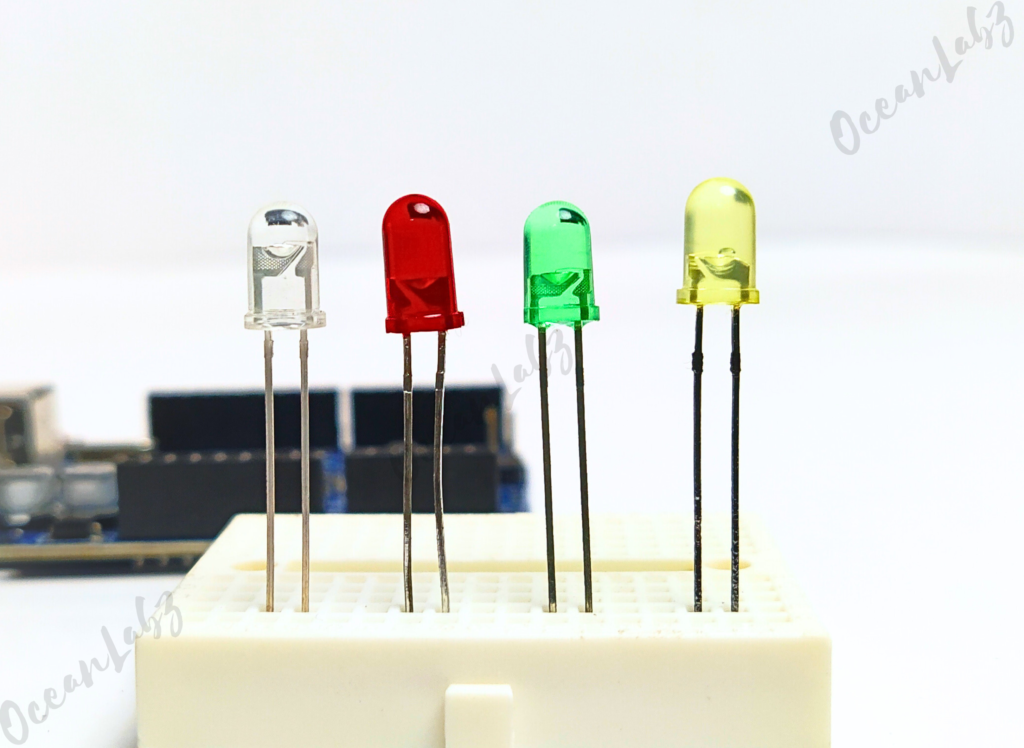
The LED is one of the simplest and most popular electronic components. It is used to indicate the status of a device, create visual effects, and much more. In this tutorial, you will learn how to control an LED using an Arduino.
Required Components
- Arduino UNO R3 SMD
- 5 mm LED
- 220-ohm resistor
- Breadboard
- Jumper wires
Pinout
Circuit Diagram / Wiring
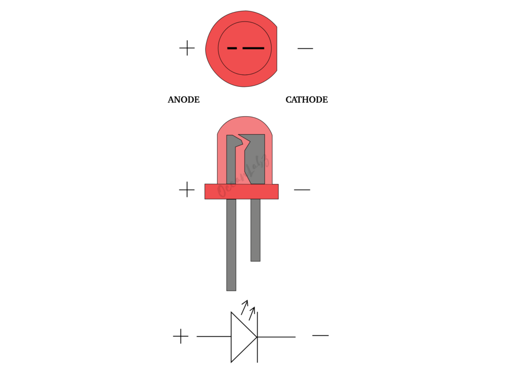
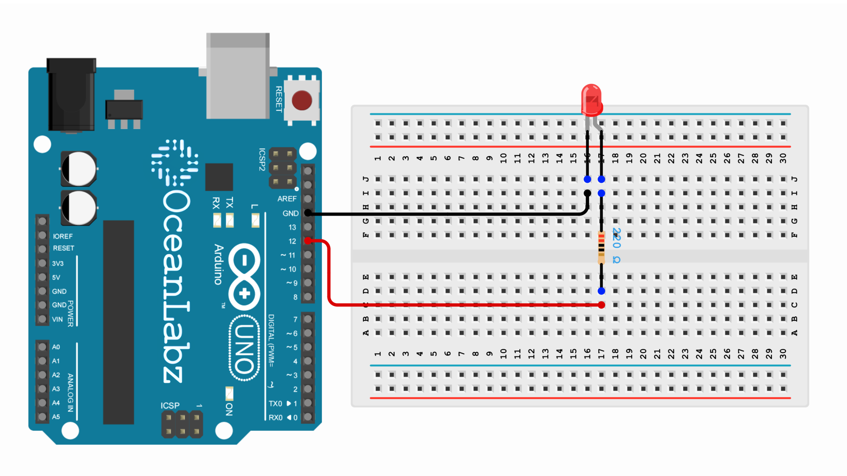
- Connect the longer leg (anode) of the LED to digital pin 12 through a 220-ohm resistor.
- Connect the shorter leg (cathode) to the GND pin.
Arduino Code / Programming
- Open the Arduino IDE.
- Go to Tools > Board and select your Arduino board (e.g., Arduino Uno).
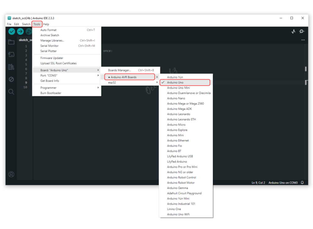
- Go to Tools > Port and select the port to which your Arduino is connected.
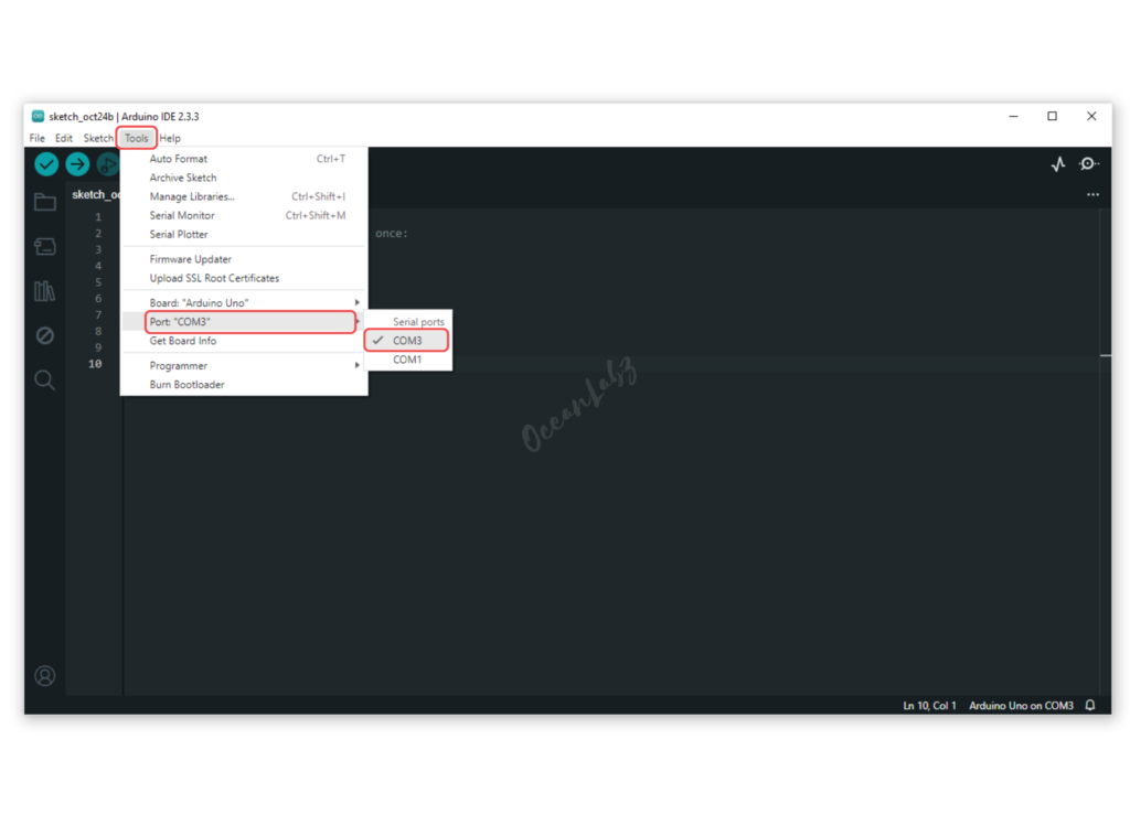
- Copy the provided code into your Arduino IDE.
int ledPin = 12; // Pin where the LED is connected

void setup() {
  pinMode(ledPin, OUTPUT); // Set the LED pin as output
}

void loop() {
  digitalWrite(ledPin, HIGH); // Turn the LED on
  delay(1000);                // Wait for 1 second
  digitalWrite(ledPin, LOW);  // Turn the LED off
  delay(1000);                // Wait for 1 second
}
- Verify and upload the code to your Arduino board.
Explanation of the Code
- This code turns the LED on and off in 1-second intervals.
- The
setup()function sets the LED pin as an output, and theloop()function repeatedly toggles the LED state.
Testing and Troubleshooting
- If the LED doesn’t blink, double-check the wiring and the resistor value.
- Ensure that the LED is connected correctly (anode to pin 12, cathode to GND).
Arduino Projects:
Arduino project 1 – Fibonacci Blink Sequence with LED
This Arduino project makes an LED blink according to the Fibonacci sequence, with the LED connected to pin 12. The Fibonacci sequence begins with 0 and 1, where each subsequent number is the sum of the previous two. Starting from the second Fibonacci number (1), the LED’s ON time is determined in milliseconds, while the OFF time remains fixed at 500 milliseconds. To maintain a practical blink pattern, the maximum ON time is limited to 8 seconds (8000 milliseconds). Once this limit is reached, the sequence resets and starts over, ensuring a continuous and dynamic blinking pattern.
Arduino Code
const int ledPin = 12;     // LED connected to digital pin 12
int prev = 0, curr = 1;    // Variables to hold Fibonacci numbers

void setup() {
  pinMode(ledPin, OUTPUT); // Set LED pin as output
  Serial.begin(9600);      // Start Serial communication at 9600 baud rate
}

void loop() {
  // Blink the LED using the current Fibonacci number for ON time
  digitalWrite(ledPin, HIGH);
  Serial.print("LED ON for ");
  Serial.print(curr);
  Serial.println(" seconds");
  delay(curr * 1000);      // ON time in milliseconds (1 sec = 1000ms)

  digitalWrite(ledPin, LOW);
  Serial.println("LED OFF for 0.5 seconds");
  delay(500);              // OFF time fixed at 500ms

  // Generate next Fibonacci number
  int next = prev + curr;
  prev = curr;
  curr = next;

  // Print the next Fibonacci number
  Serial.print("Next Fibonacci Number: ");
  Serial.println(curr);

  // Limit the ON time to 8 seconds
  if (curr > 8) {
    Serial.println("Resetting Fibonacci sequence");
    prev = 0;
    curr = 1;
  }
}
Explanation
- LED blinks with ON durations based on Fibonacci numbers (up to 8 seconds) and a 0.5-second OFF time.
- Fibonacci sequence resets automatically after 8 seconds.
- Logs LED states and Fibonacci numbers to the Serial Monitor.
- Pin 12 is used for LED output, and timing is managed with
delay().
Arduino project 2 – LED Strobe with Increasing Speed
This Arduino project creates a strobe light effect using an LED connected to pin 12. The strobe starts at a slow blink rate (1-second ON and OFF), progressively speeds up by reducing the delay time by 10% after each blink, and resets once it reaches a minimum speed of 100ms ON and OFF. This dynamic effect is perfect for learning how to control timing and create visually engaging patterns with Arduino.
Arduino Code
const int ledPin = 12;     // LED connected to digital pin 12
int delayTime = 1000;      // Initial delay time (in milliseconds)

void setup() {
  pinMode(ledPin, OUTPUT); // Set LED pin as output
}

void loop() {
  // Blink the LED
  digitalWrite(ledPin, HIGH);
  delay(delayTime);        // ON time
  digitalWrite(ledPin, LOW);
  delay(delayTime);        // OFF time

  // Decrease the delay time by 10% each cycle
  delayTime = delayTime * 0.9;

  // Ensure the delay time doesn't go below 100ms
  if (delayTime < 100) {
    delayTime = 1000;  // Reset to the original delay time
  }
}
Explanation
Initial Setup:
- The LED is connected to pin 12, configured as an output.
- The initial delay time (
delayTime) is set to 1000 milliseconds (1 second).
LED Blinking:
- In each loop, the LED turns ON for
delayTimemilliseconds, then OFF for the same duration.
Decreasing Delay Time:
- After each blink cycle, the delay time reduces by 10% (
delayTime = delayTime * 0.9), making the LED blink faster over time.
Reset Condition:
- To prevent the delay from becoming too short, the minimum delay time is capped at 100 milliseconds. If it reaches this value,
delayTimeresets to 1000 milliseconds to start the cycle over again.
Arduino project 3 – Prime Number Blinker with LED
In this Arduino project, an LED connected to pin 12 blinks in a pattern determined by prime numbers. The LED stays ON for a duration equal to the next prime number in the sequence (measured in milliseconds), starting from 2. After each ON time, the LED turns OFF for 500 milliseconds. Once a prime number exceeds 100 milliseconds, the pattern resets, starting over from the first prime number. This project showcases how to use prime numbers to control timing and create dynamic blink patterns.
Arduino Code
const int ledPin = 12;  // LED connected to digital pin 12
int primeNumbers[] = {2, 3, 5, 7, 11, 13, 17, 19, 23, 29, 31, 37, 41, 43, 47};  // Array of prime numbers
int primeIndex = 0;

void setup() {
  pinMode(ledPin, OUTPUT);  // Set LED pin as output
}

void loop() {
  // Blink the LED based on prime numbers
  digitalWrite(ledPin, HIGH);
  delay(primeNumbers[primeIndex] * 100); // ON time (prime number * 100ms)
  digitalWrite(ledPin, LOW);
  delay(500); // OFF time

  // Move to the next prime number
  primeIndex++;

  // If we exceed the list of prime numbers, reset
  if (primeIndex >= sizeof(primeNumbers) / sizeof(primeNumbers[0])) {
    primeIndex = 0;
  }
}
Explanation
Initial Setup:
- The LED is connected to pin 12, and it is configured as an output.
- An array of prime numbers is defined to control the ON time of the LED.
Blinking Logic:
- In each loop, the LED turns ON for a duration determined by a prime number from the array, multiplied by 100 milliseconds (e.g., 2 * 100ms = 200ms).
- After each ON time, the LED turns OFF for a fixed duration of 500 milliseconds.
Prime Number Cycling:
- The program moves through the array of prime numbers, using each one for the LED’s ON time.
- Once the program reaches the end of the list, it resets the index to start over with the first prime number.


