Index
Introduction
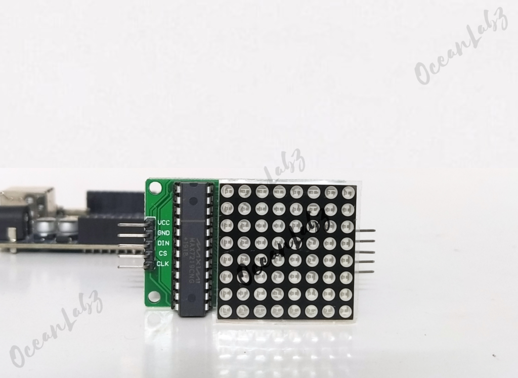
The MAX7219 8×8 LED Matrix module is a versatile component used to display text, numbers, and animations. It simplifies the process of controlling individual LEDs in the 8×8 matrix using the MAX7219 chip. This tutorial will guide you through setting up the module and programming it to display simple patterns using an Arduino.
Required Components
- Arduino UNO R3 SMD
- 8×8 LED Matrix Display Module
- Jumper wires
- Breadboard
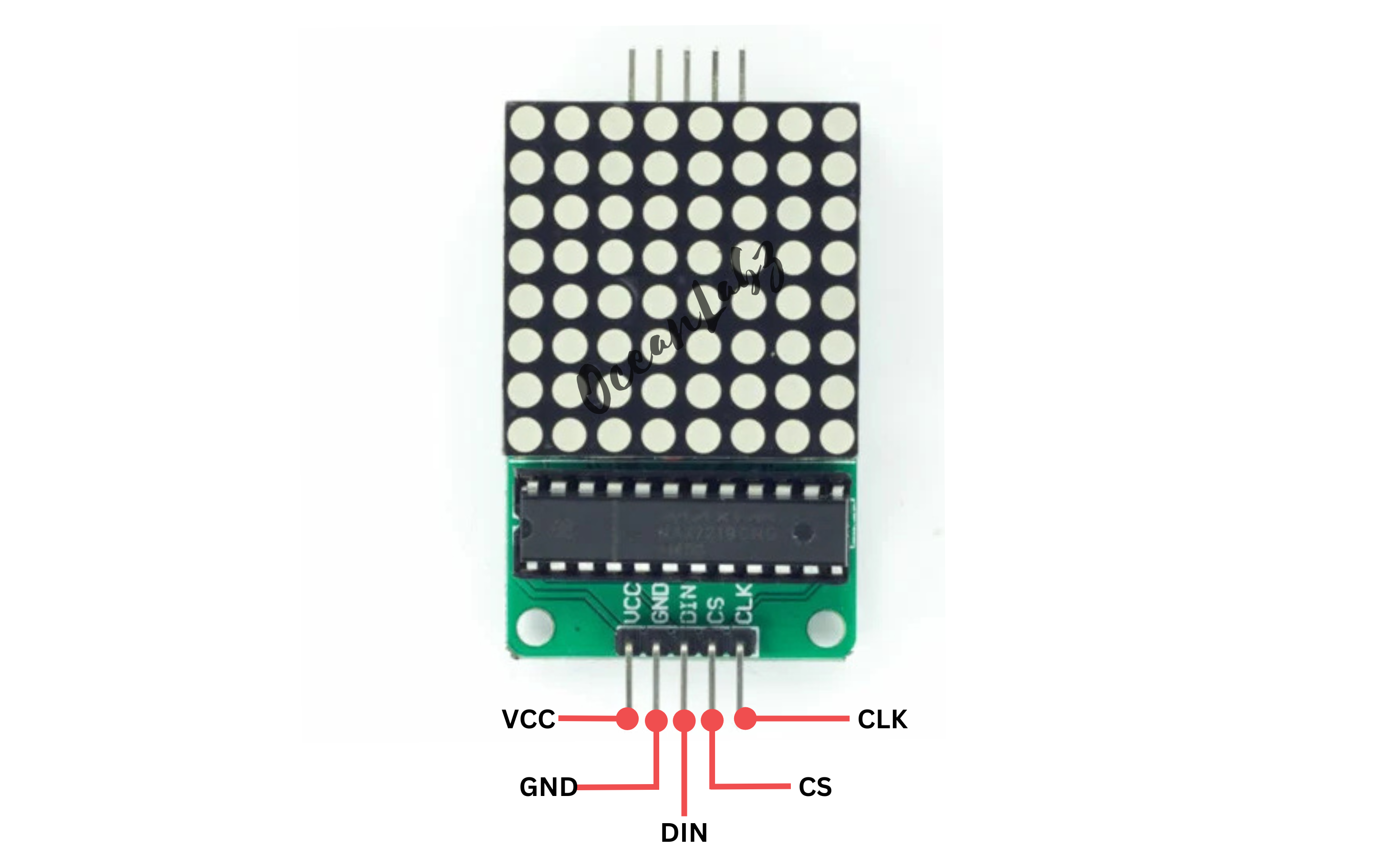
Pinout
Circuit Diagram / Wiring
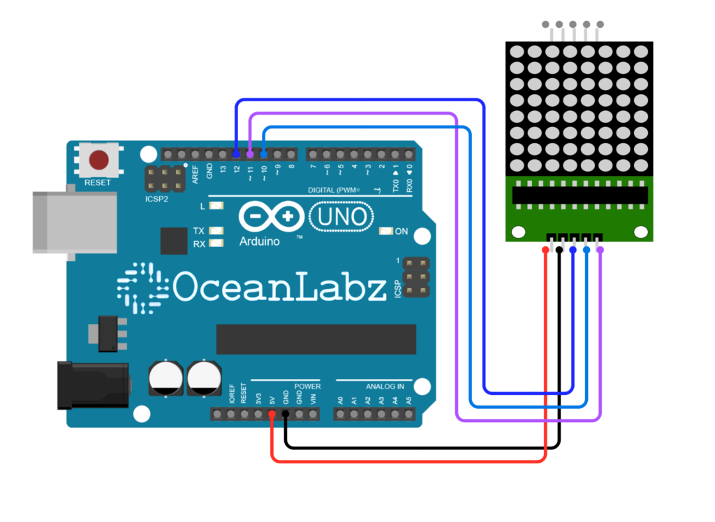
- VCC (LED Module) → 5V (Arduino)
- GND (LED Module) → GND (Arduino)
- DIN (LED Module) → Pin 12 (Arduino)
- CS (LED Module) → Pin 11 (Arduino)
- CLK (LED Module) → Pin 10 (Arduino)
Arduino Code / Programming
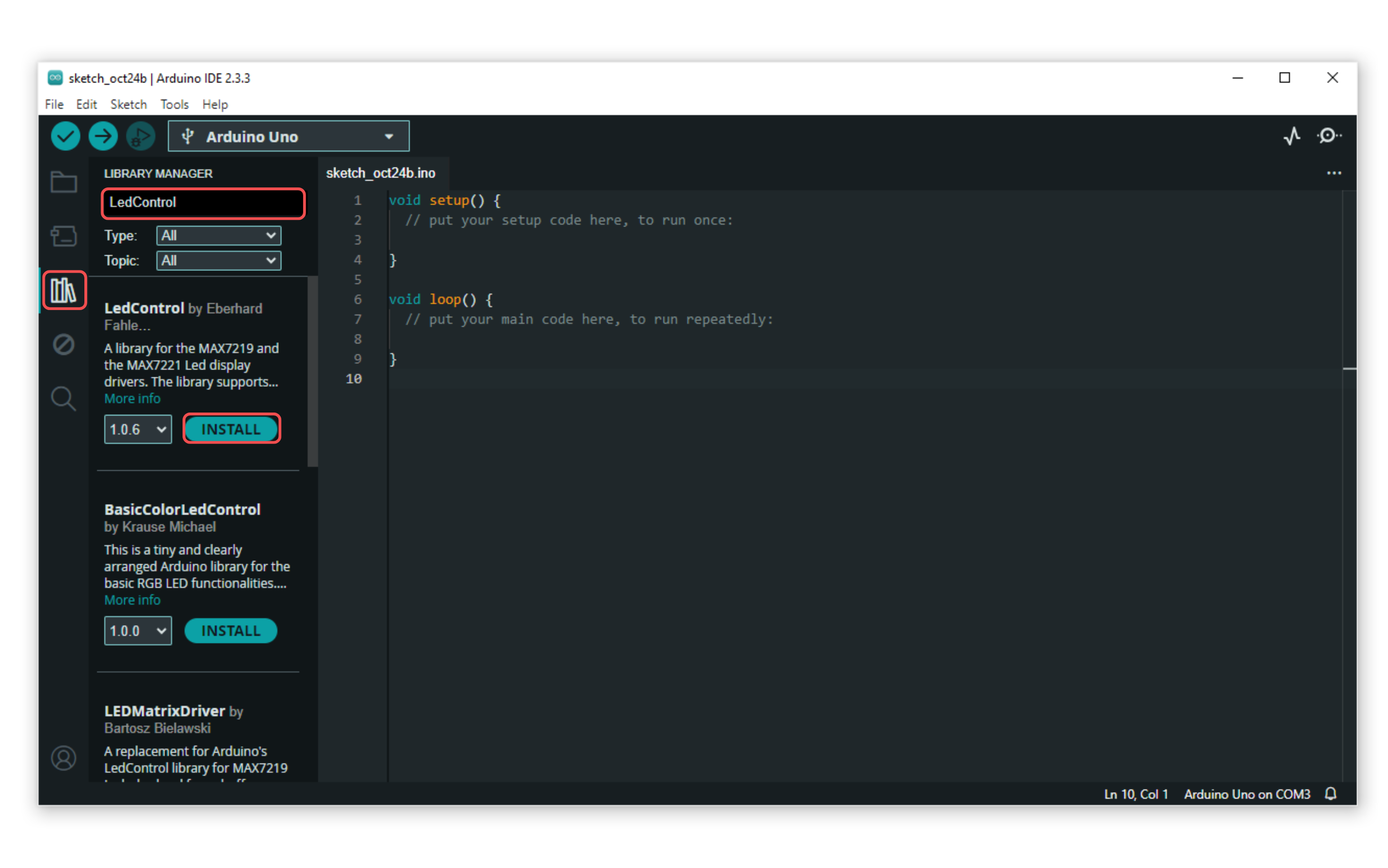
- Go to the “Libraries” tab on the left-hand side of the screen.
- Click on the “Library Manager” button (book icon) at the top of the Libraries tab.
- In the Library Manager window, type “LedControl” in the search bar.
- Locate the “LedControl” library click on the “Install” button next to it.
- Wait for the library to be installed, and you’re ready to use the LedControl library in your projects.
- Use the following code to display a simple pattern on the LED Matrix:
#include <LedControl.h>

// Define pins for DIN, CLK, and CS
#define DATA_IN 12
#define CLK 11
#define CS 10


// Create an instance of LedControl
LedControl lc = LedControl(DATA_IN, CLK, CS, 1); // DataIn, Clock, ChipSelect, Number of devices

void setup() {
  // Initialize the MAX7219 device
  lc.shutdown(0, false);      // Wake up the display
  lc.setIntensity(0, 8);      // Set brightness level (0-15)
  lc.clearDisplay(0);         // Clear the display
}

void loop() {
  // Display each emoji in sequence
  displayNormalFace();
  delay(1000); // Show normal face for 1 second

  lc.clearDisplay(0); // Clear display
  delay(500); // Small delay before the next emoji

  displayHeart();
  delay(1000); // Show heart for 1 second

  lc.clearDisplay(0); // Clear display
  delay(500); // Small delay before the next emoji

  displaySmileFace();
  delay(1000); // Show smile face for 1 second

  lc.clearDisplay(0); // Clear display
  delay(500); // Small delay before repeating the sequence
}

void displayNormalFace() {
  // Pattern for a normal face
  byte normalFace[8] = {
    B00111100,
    B01000010,
    B10100101,
    B10000001,
    B10000001,
    B10111101,
    B01000010,
    B00111100
  };

  // Set each row of the matrix
  for (int row = 0; row < 8; row++) {
    lc.setRow(0, row, normalFace[row]);
  }
}

void displayHeart() {
  // Pattern for a heart shape
  byte heart[8] = {
    B00000000,
    B01100110,
    B11111111,
    B11111111,
    B11111111,
    B01111110,
    B00111100,
    B00011000
  };

  // Set each row of the matrix
  for (int row = 0; row < 8; row++) {
    lc.setRow(0, row, heart[row]);
  }
}

void displaySmileFace() {
  // Pattern for a smile face
  byte smileFace[8] = {
    B00111100,
    B01000010,
    B10100101,
    B10000001,
    B10100101,
    B10011001,
    B01000010,
    B00111100
  };

  // Set each row of the matrix
  for (int row = 0; row < 8; row++) {
    lc.setRow(0, row, smileFace[row]);
  }
}
Explanation of the Code
- LedControl Library: The library simplifies communication with the MAX7219 driver, allowing easy control of the matrix.
- Setup Function: Initializes the LED matrix, sets the brightness, and clears the display.
- Sequence: It will show the normal face, followed by the heart, and then the smile face, repeating continuously.
Arduino Projects:
Arduino project 1 – Snake Game with Matrix Display and push button
This code is a simple Snake game built for an 8×8 LED matrix using the MAX7219 driver module and Arduino. Below is a breakdown of how the game works:
Required Components
- Arduino UNO
- 8×8 LED Matrix Display Module
- tandalone Tactile Push Button (4)
- 10kΩ resistor (4)
- Jumper wires
- Breadboard
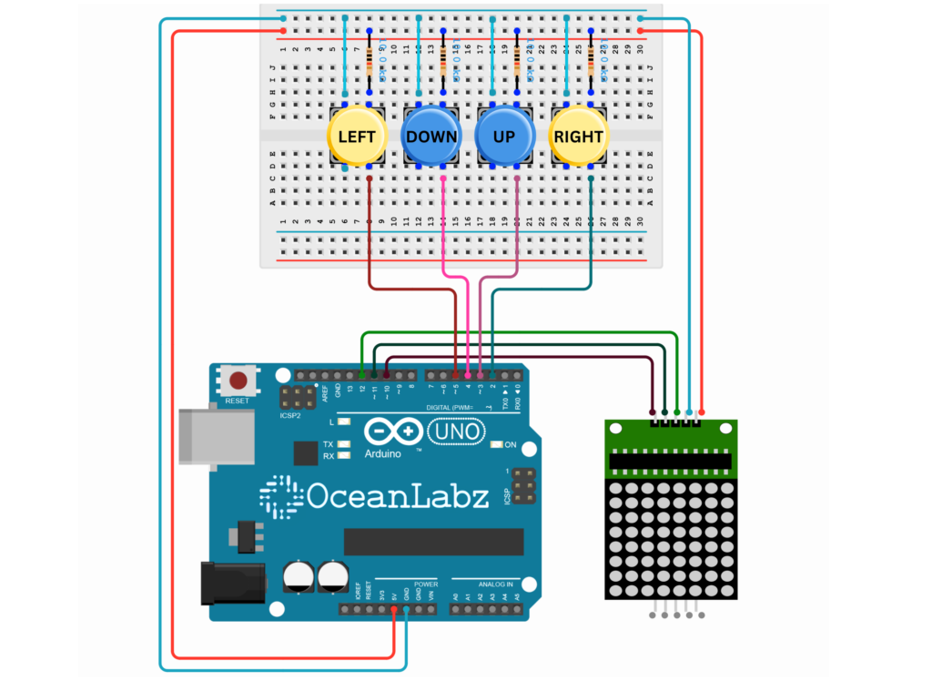
Circuit Diagram / Wiring
- MAX7219 (LED Matrix) Connections:
- VCC (LED Module) → 5V (Arduino)
- GND (LED Module) → GND (Arduino)
- DIN (LED Module) → Pin 12 (Arduino)
- CS (LED Module) → Pin 11 (Arduino)
- CLK (LED Module) → Pin 10 (Arduino)
- Push Buttons:
- Up Button → Pin 3 on Arduino (with a 10kΩ resistor to 5V)
- Down Button → Pin 4 on Arduino (with a 10kΩ resistor to 5V)
- Left Button → Pin 5 on Arduino (with a 10kΩ resistor to 5V)
- Right Button → Pin 2 on Arduino (with a 10kΩ resistor to 5V)
Arduino Code
#include <LedControl.h>  // MAX7219 control library

// Define MAX7219 pins
#define DATA_IN 12
#define CLK 10
#define CS 11


LedControl lc = LedControl(DIN_PIN, CLK_PIN, CS_PIN, 1);

// Push buttons
#define UP_BTN 3
#define DOWN_BTN 4
#define LEFT_BTN 5
#define RIGHT_BTN 2

// Game variables
int snake[64][2]; // Snake body (maximum length 64)
int snakeLength = 2; // Starting length of the snake
int direction = 1;   // 0=UP, 1=RIGHT, 2=DOWN, 3=LEFT
int foodX, foodY;
bool isGameOver = false;

void setup() {
  // Initialize MAX7219
  lc.shutdown(0, false);
  lc.setIntensity(0, 8);  // Set brightness (0-15)
  lc.clearDisplay(0);

  // Initialize buttons
  pinMode(UP_BTN, INPUT_PULLUP);
  pinMode(DOWN_BTN, INPUT_PULLUP);
  pinMode(LEFT_BTN, INPUT_PULLUP);
  pinMode(RIGHT_BTN, INPUT_PULLUP);

  // Initialize Serial Monitor
  Serial.begin(9600);
  Serial.println("Game Started! Use buttons to control the snake.");

  // Initialize snake position
  snake[0][0] = 3; snake[0][1] = 3; // Head
  snake[1][0] = 3; snake[1][1] = 2; // Body

  generateFood(); // Generate the first food
}

void loop() {
  if (isGameOver) {
    gameOver();
    return;
  }

  // Read buttons for direction
  if (!digitalRead(UP_BTN) && direction != 2) direction = 0;
  if (!digitalRead(RIGHT_BTN) && direction != 3) direction = 1;
  if (!digitalRead(DOWN_BTN) && direction != 0) direction = 2;
  if (!digitalRead(LEFT_BTN) && direction != 1) direction = 3;

  moveSnake();

  if (checkCollision()) {
    isGameOver = true;
    return;
  }

  if (checkFood()) {
    snakeLength++;
    Serial.print("Food eaten! New length: ");
    Serial.println(snakeLength);
    generateFood();
  }

  displaySnake();
  delay(300); // Adjust speed of the game
}

void moveSnake() {
  // Move body
  for (int i = snakeLength - 1; i > 0; i--) {
    snake[i][0] = snake[i - 1][0];
    snake[i][1] = snake[i - 1][1];
  }

  // Move head
  if (direction == 0) snake[0][0]--; // UP
  if (direction == 1) snake[0][1]++; // RIGHT
  if (direction == 2) snake[0][0]++; // DOWN
  if (direction == 3) snake[0][1]--; // LEFT

  // Print direction to Serial Monitor
  Serial.print("Snake moved: ");
  if (direction == 0) Serial.println("UP");
  if (direction == 1) Serial.println("RIGHT");
  if (direction == 2) Serial.println("DOWN");
  if (direction == 3) Serial.println("LEFT");
}

bool checkCollision() {
  // Check wall collision
  if (snake[0][0] < 0 || snake[0][0] >= 8 || snake[0][1] < 0 || snake[0][1] >= 8) {
    Serial.println("Collision with wall! Game Over.");
    return true;
  }
  // Check self-collision
  for (int i = 1; i < snakeLength; i++) {
    if (snake[0][0] == snake[i][0] && snake[0][1] == snake[i][1]) {
      Serial.println("Collision with self! Game Over.");
      return true;
    }
  }
  return false;
}

bool checkFood() {
  return snake[0][0] == foodX && snake[0][1] == foodY;
}

void generateFood() {
  do {
    foodX = random(0, 8);
    foodY = random(0, 8);
  } while (isFoodOnSnake());

  Serial.print("New food generated at: (");
  Serial.print(foodX);
  Serial.print(", ");
  Serial.print(foodY);
  Serial.println(")");
}

bool isFoodOnSnake() {
  for (int i = 0; i < snakeLength; i++) {
    if (foodX == snake[i][0] && foodY == snake[i][1]) {
      return true;
    }
  }
  return false;
}

void displaySnake() {
  lc.clearDisplay(0);

  // Display snake
  for (int i = 0; i < snakeLength; i++) {
    lc.setLed(0, snake[i][0], snake[i][1], true);
  }

  // Display food
  lc.setLed(0, foodX, foodY, true);
}

void gameOver() {
  lc.clearDisplay(0);
  for (int i = 0; i < 8; i++) {
    for (int j = 0; j < 8; j++) {
      lc.setLed(0, i, j, true);
    }
  }
  Serial.println("Game Over! Restarting...");
  delay(3000);
  setup(); // Restart the game
}
Explanation
- Implements a Snake game on an 8×8 LED matrix using MAX7219 and Arduino.
- Four push buttons control the snake’s movement (UP, DOWN, LEFT, RIGHT).
- Snake grows by eating randomly generated food and avoids collisions with walls or itself.
- LED matrix visually updates the game state, and the Serial Monitor logs events like direction, food eaten, and Game Over.
Arduino project 2 – Creating a Audio Spectrum Visualizer with Matrix Display and Sound Sensor
The Audio Spectrum Visualizer is an interactive project that uses an 8×8 LED Matrix and a Sound Sensor to display real-time audio intensity as a dynamic visual pattern. It works by reading sound levels, processing them with an Arduino, and lighting up the matrix rows based on the audio signal’s amplitude. Perfect for learning electronics and creating visually engaging sound displays!
Required Components
- Arduino UNO
- 8×8 LED Matrix Display Module
- Sound Sensor
- Jumper wires
- Breadboard
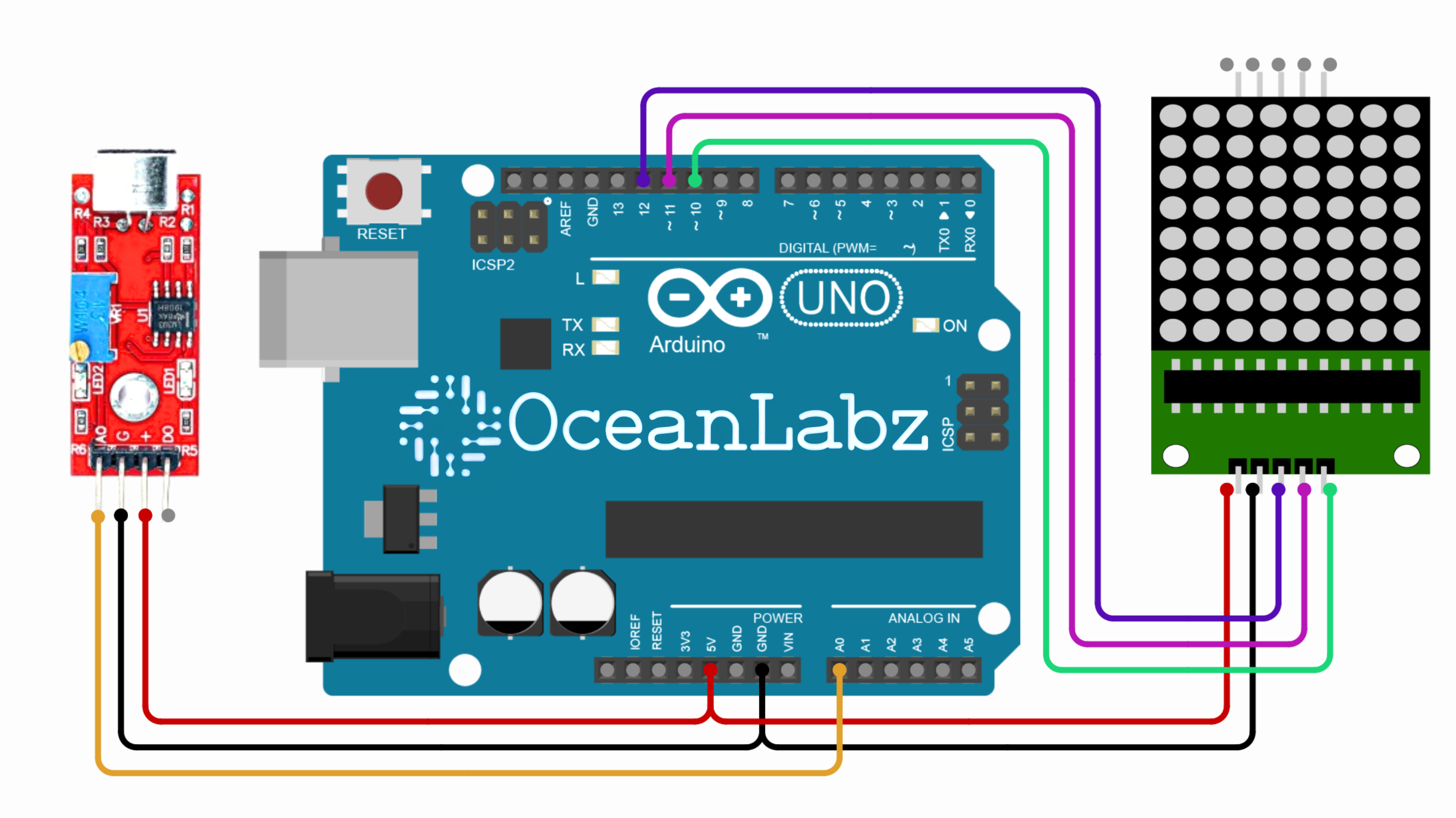
Circuit Diagram / Wiring
- MAX7219 (LED Matrix) to Arduino
- VCC (LED Module) → 5V (Arduino)
- GND (LED Module) → GND (Arduino)
- DIN (LED Module) → Pin 12 (Arduino)
- CS (LED Module) → Pin 11 (Arduino)
- CLK (LED Module) → Pin 10 (Arduino)
- Sound Sensor to Arduino:
- VCC (Sound Sensor) → 5V (Arduino)
- GND (Sound Sensor) → GND (Arduino)
- AO (Sound Sensor) → A0 (Arduino)
Arduino Code
#include <LedControl.h>

// Define pins for DIN, CLK, and CS
#define DATA_IN 12
#define CLK 10
#define CS 11

// Create an instance of LedControl
LedControl lc = LedControl(DATA_IN, CLK, CS, 1); // DataIn, Clock, ChipSelect, Number of devices

const int sampleWindow = 50; // Sample window width in ms
const int maxScale = 8;      // Max height of visualizer

byte ledMatrix[8] = {0}; // Array to hold LED states for each row

void setup() {
  lc.shutdown(0, false); // Wake up the display
  lc.setIntensity(0, 8); // Set brightness level (0-15)
  lc.clearDisplay(0);    // Clear the display
}

void loop() {
  // Read sound level
  int soundLevel = readSoundLevel();

  // Shift the matrix left to create scrolling effect
  for (int row = 0; row < 8; row++) {
    ledMatrix[row] >>= 1; // Shift right to scroll left
  }

  // Update new sound level column
  for (int row = 0; row < 8; row++) {
    if (row < soundLevel) {
      ledMatrix[row] |= 0x80; // Set highest bit for new column
    }
  }

  // Push the updated ledMatrix to the display
  for (int row = 0; row < 8; row++) {
    lc.setRow(0, row, ledMatrix[row]);
  }

  delay(50); // Small delay for smoother visualization
}

// Function to simulate sound level reading
int readSoundLevel() {
  unsigned long startMillis = millis();
  unsigned int signalMax = 0;
  unsigned int signalMin = 1024;

  while (millis() - startMillis < sampleWindow) {
    int sample = analogRead(A0);
    if (sample > signalMax) signalMax = sample;
    if (sample < signalMin) signalMin = sample;
  }

  int peakToPeak = signalMax - signalMin;
  return map(peakToPeak, 0, 1023, 0, maxScale); // Map sound level to matrix height
}
Explanation
- The code visualizes sound levels on an 8×8 LED Matrix by reading audio input using a sound sensor.
- It calculates the peak-to-peak sound amplitude and maps it to the matrix’s height.
- A scrolling effect is achieved by shifting previous data and updating the display with new sound levels.
Testing and Troubleshooting
- Connections: Double-check all wiring and ensure the pins are connected correctly.
- Power Supply: Ensure that the module is powered with the 5V from the Arduino.
- Library Installation: Make sure the
LedControllibrary is properly installed.


