Index
Introduction
The MPU6050 is a sensor module used in things like robots and drones. It has six different functions that help it measure movement accurately and is well-liked for being both precise and affordable. In this blog post, we’ll learn about what the MPU6050 is, how it does its job, what its technical details are, and how to connect it to an Arduino for your projects.
Working Principle
- Gyroscope:
The MPU6050 consist of 3-axis Gyroscope with Micro Electro Mechanical System(MEMS) technology. It is used to detect rotational velocity along the X, Y, Z axes as shown in below figure.
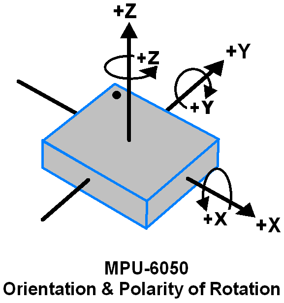
When the gyros are rotated about any of the sense axes, the Coriolis Effect causes a vibration that is detected by a MEM inside MPU6050.
– The resulting signal is amplified, demodulated, and filtered to produce a voltage that is proportional to the angular rate.
– This voltage is digitized using 16-bit ADC to sample each axis.
– The full-scale range of output are +/- 250, +/- 500, +/- 1000, +/- 2000.
– It measures the angular velocity along each axis in degree per second unit.
- Accelerometer:
The MPU6050 consist 3-axis Accelerometer with Micro Electro Mechanical (MEMs) technology. It used to detect angle of tilt or inclination along the X, Y and Z axes as shown in below figure.
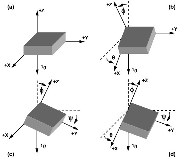
– Acceleration along the axes deflects the movable mass.
– This displacement of moving plate (mass) unbalances the differential capacitor which results in sensor output. Output amplitude is proportional to acceleration.
– 16-bit ADC is used to get digitized output.
– The full-scale range of acceleration are +/- 2g, +/- 4g, +/- 8g, +/- 16g.
– It measured in g (gravity force) unit.
– When device placed on flat surface it will measure 0g on X and Y axis and +1g on Z axis.
Application
- Robotics and Drones: Provides motion data for stabilization and control.
- Gesture Recognition: Enables control of devices through motion-based commands.
- Gaming and VR: Tracks user movements for interactive experiences.
- Motion Capture: Used in animation and virtual reality for accurate movement tracking.
- Navigation and Positioning: Estimates orientation and movement for navigation systems.
- Health and Fitness: Measures physical activities in fitness trackers and health devices.
Technical Specifications
- Type: MPU6050 3-Axis Accelerometer and Gyro Sensor
- Axes: 3-axis accelerometer, 3-axis gyroscope
- Output: Digital (I2C)
- Applications: Motion sensing, orientation tracking
- Compatibility: Arduino, Raspberry Pi
- Mounting: Compact design
- Versatility: Suitable for various projects
Pinout
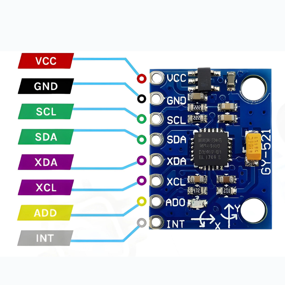
- VCC: Connect to 3.3V or 5V power supply.
- GND: Connect to ground (0V).
- SDA: I2C serial data line for communication with microcontroller.
- SCL: I2C serial clock line for communication with microcontroller.
- AD0: I2C address selection (connect to VCC or GND to set address).
- XDA and XCL: Auxiliary I2C interface (not commonly used).
- INT: Optional interrupt output pin for triggering events.
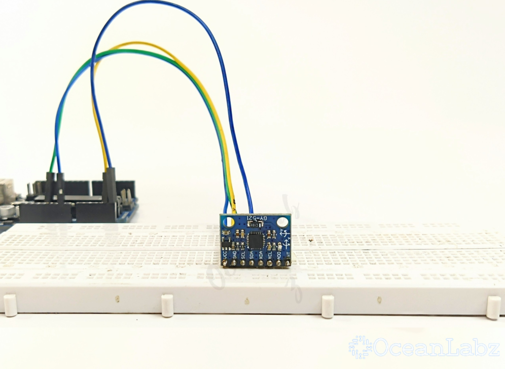
Circuit Diagram
| MPU6050 Pin | Arduino Pin |
| VCC | 5 V |
| GND | GND |
| SDA | Analog A4 |
| SCL | Analog A5 |

Programming With Arduino
Step 1: Open your first sketch
- Open the Arduino IDE.
- Copy and paste the provided code into a new sketch in the Arduino IDE:
#include <Wire.h>
#include <MPU6050.h>

MPU6050 mpu;

void setup() {
  Serial.begin(9600);

  // Initialize the MPU6050
  Wire.begin();
  mpu.initialize();

  // Check if the MPU6050 is connected
  if (!mpu.testConnection()) {
    Serial.println("MPU6050 connection failed");
    while (1);
  }
}

void loop() {
  // Read accelerometer and gyroscope values
  int16_t ax, ay, az;
  int16_t gx, gy, gz;

  mpu.getMotion6(&ax, &ay, &az, &gx, &gy, &gz);

  // Print the values
  Serial.print("Acceleration: ");
  Serial.print("X = "); Serial.print(ax);
  Serial.print(", Y = "); Serial.print(ay);
  Serial.print(", Z = "); Serial.println(az);

  Serial.print("Gyroscope: ");
  Serial.print("X = "); Serial.print(gx);
  Serial.print(", Y = "); Serial.print(gy);
  Serial.print(", Z = "); Serial.println(gz);

  Serial.println();

  delay(1000);
}
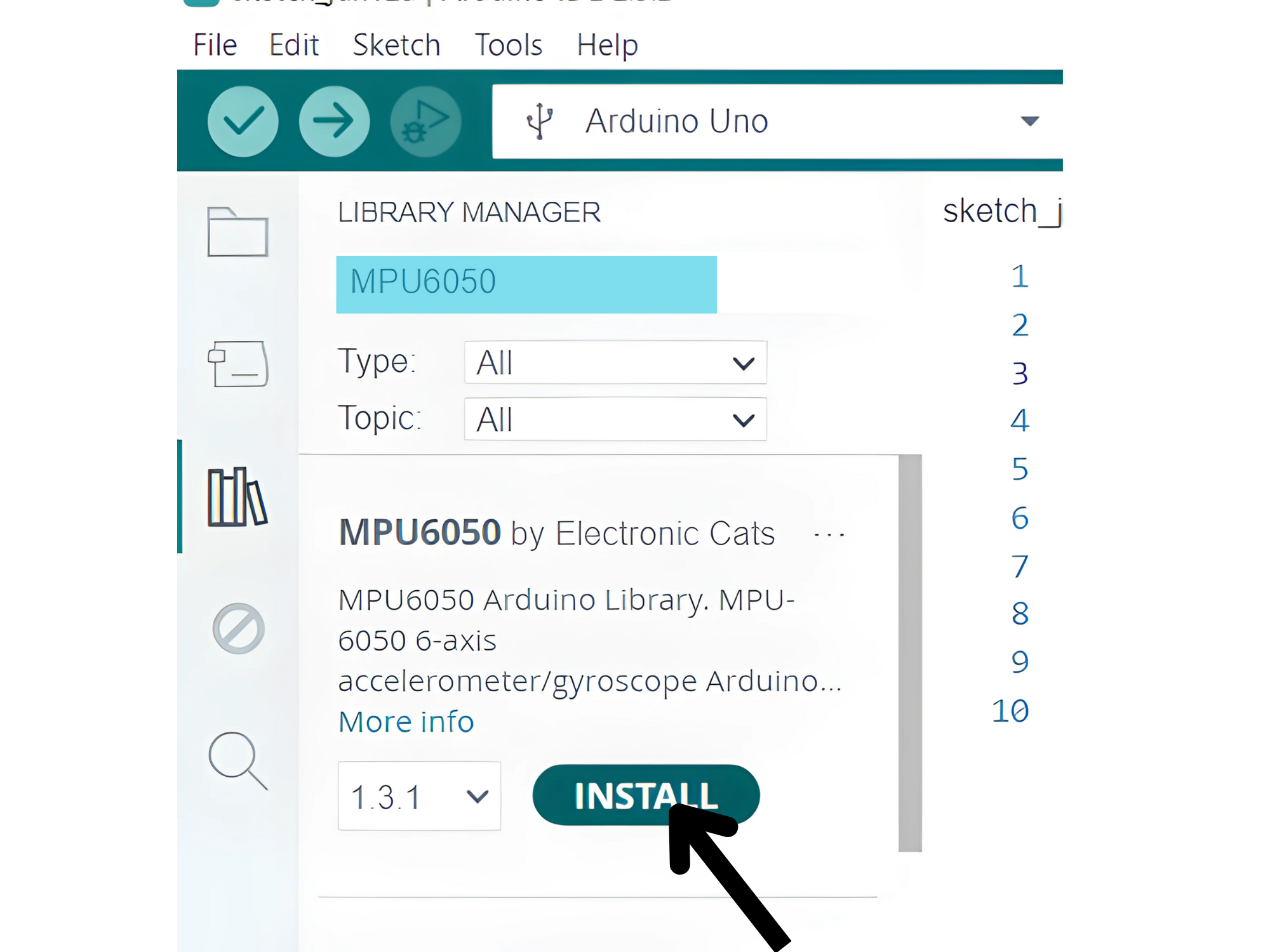
Step 2: Install the Required Library
- The Wire library is included by default with the Arduino IDE, so you do not need to install it separately.
- Go to Sketch > Tools> Manage Libraries.
Step 3: Select the appropriate board and port
- Go to Tools > Board and select your Arduino board (e.g., Arduino Uno).
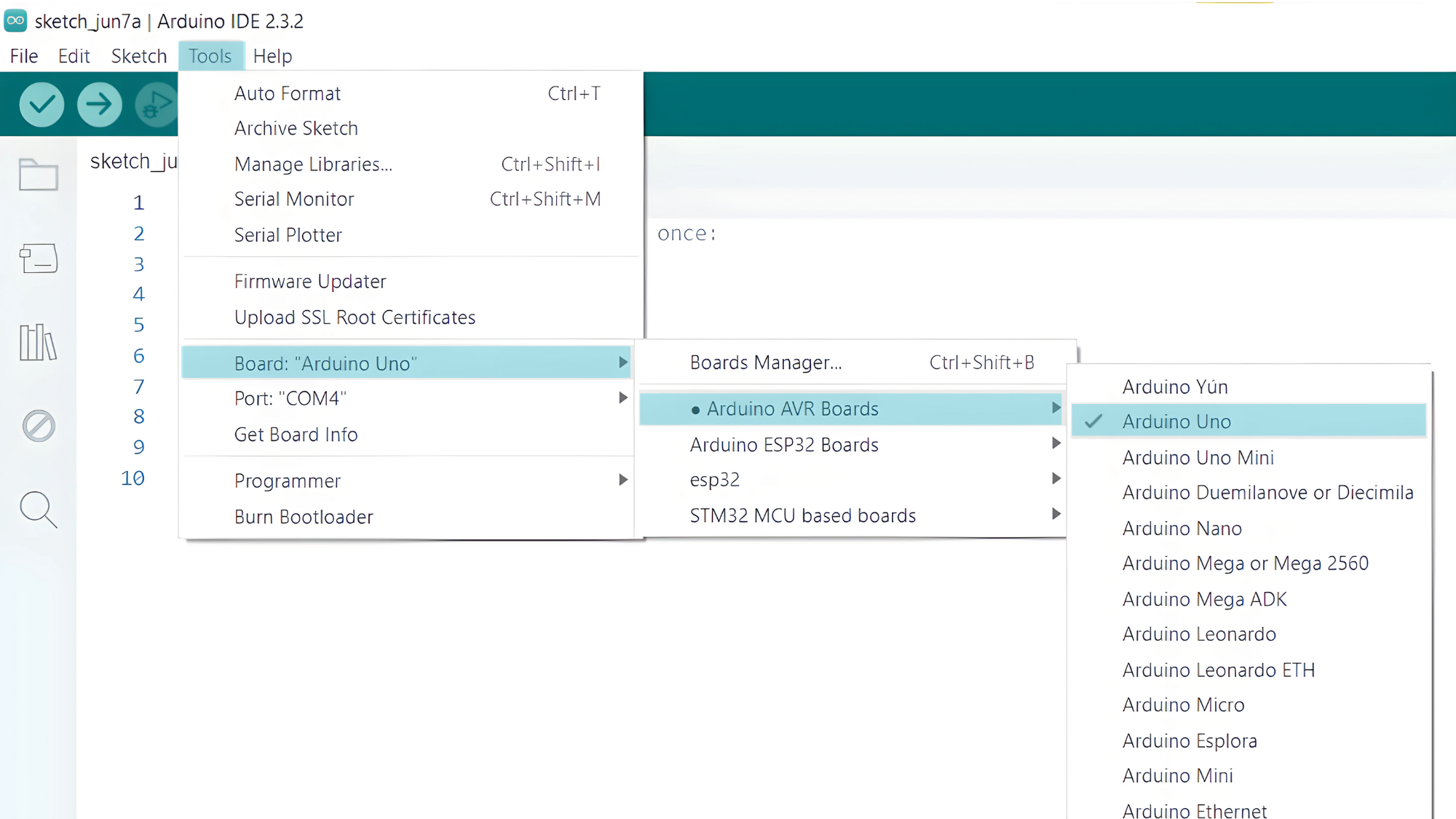
- Go to Tools > Port and select the port to which your Arduino is connected.
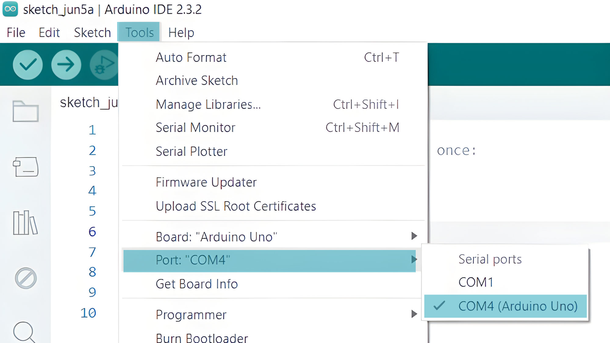
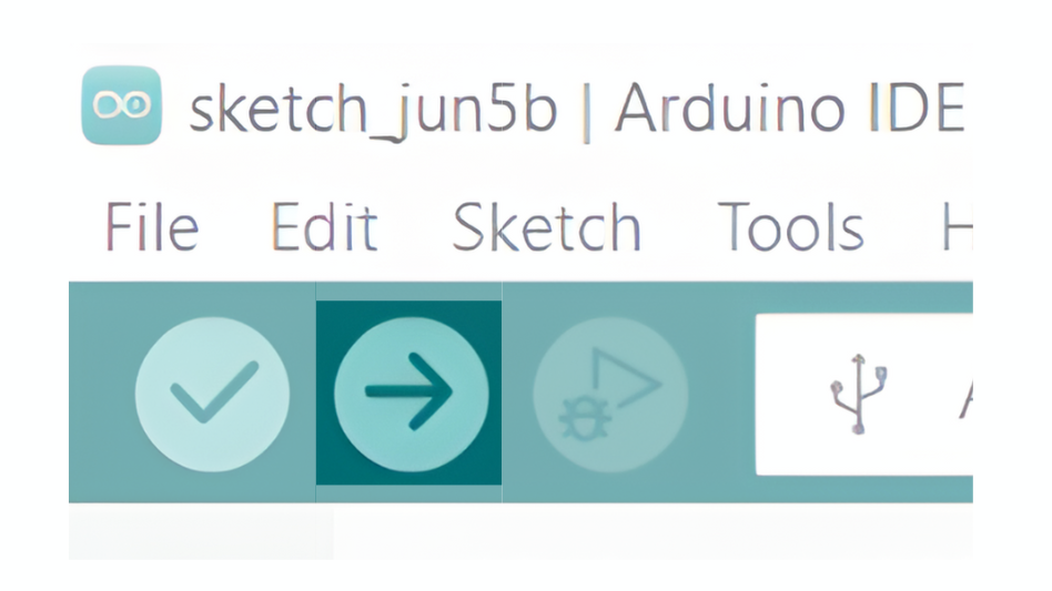
- Verify and upload the code to your Arduino board.
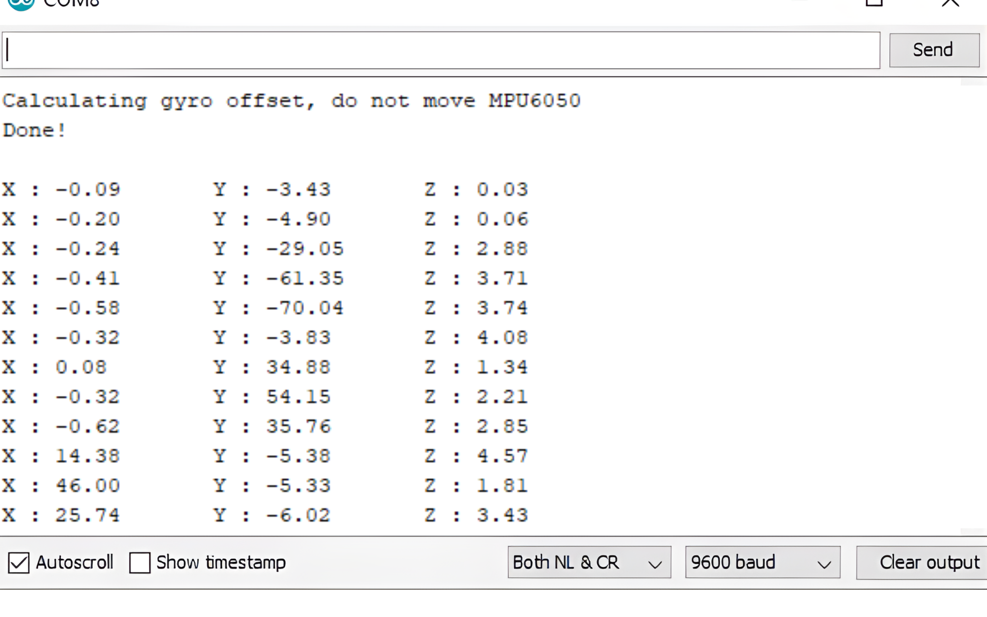
Step 4: Open the Serial Monitor
- Connect your Arduino to the computer and upload the code.
- Open the Serial Monitor in the Arduino IDE by going to Tools > Serial Monitor or pressing
Ctrl+Shift+M. - Set the baud rate to 9600 in the Serial Monitor.