Index
Introduction
The MQ-7 sensor is a carbon monoxide (CO) gas sensor. It is commonly used in applications requiring the detection of CO concentrations in the air, such as in home safety systems, industrial applications, and portable CO detectors. The sensor operates by using a tin dioxide (SnO2) semiconductor layer, which changes resistance when exposed to CO gas. This change in resistance can be measured and interpreted by a microcontroller to determine the concentration of CO in the air.
Hardware Overview

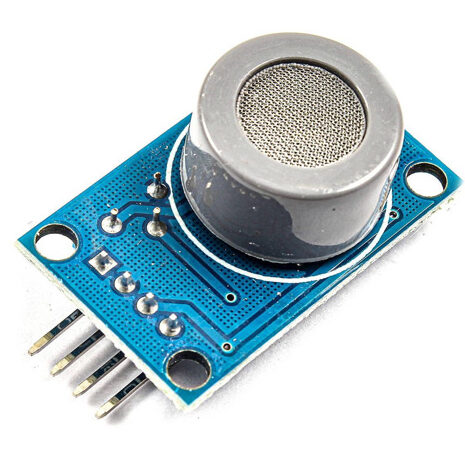
Sensor Element: The sensor element of the MQ-7 gas sensor is primarily made of tin dioxide (SnO2), a type of semiconductor material. Tin dioxide is chosen for its properties as it exhibits significant changes in electrical conductivity when exposed to various gases, particularly carbon monoxide (CO).
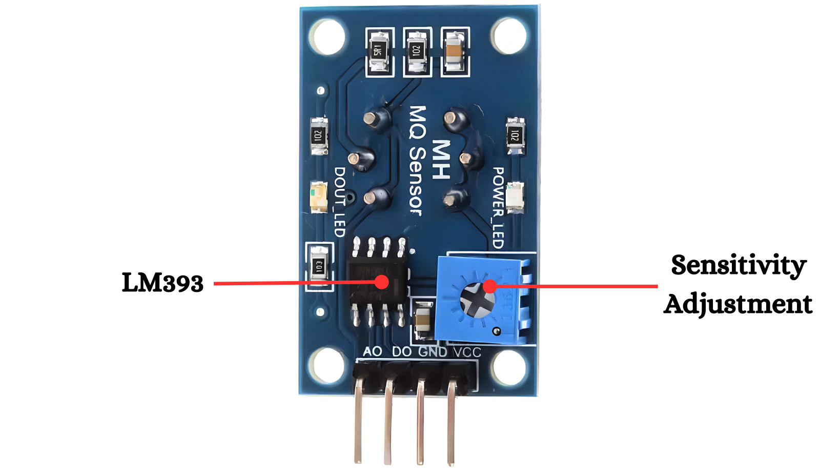
Sensitivity Adjustment: The MQ-7 sensor also includes a heating element that cycles between high and low temperatures. This cyclic heating allows the sensor to reset and clear any residual gas, ensuring that it remains sensitive and accurate over prolonged use. The sensor’s sensitivity can be fine-tuned using an external potentiometer. Adjusting this potentiometer changes the baseline resistance of the sensor in clean air, allowing it to be calibrated for different operating environments and gas concentrations.
LM393 Dual Comparator IC: The LM393 is a dual comparator integrated circuit (IC) designed to operate with a wide range of power supply voltages. It is built using bipolar junction transistor (BJT) technology, which provides reliable performance and low power consumption. The IC package typically includes two independent voltage comparators, each capable of comparing two input voltages and providing a digital output based on the comparison.
Working Principle
The MQ-7 sensor detects carbon monoxide (CO) gas through a tin dioxide (SnO2) layer whose resistance changes when exposed to CO. It uses a dual heater cycle to improve accuracy: the heater alternates between high and low temperatures, causing the SnO2 layer to react with CO and change resistance. This change is output as both an analog signal (varying voltage) and a digital signal (binary threshold indication). A microcontroller reads these signals to determine the CO concentration and can trigger alarms or other responses based on the detected levels.
Application
- Home and Industrial CO Detectors: Used to monitor and alert about dangerous carbon monoxide levels.
- Gas Leak Detection Systems: Integrated into systems to detect and respond to gas leaks.
- Environmental Monitoring: Measures CO levels for air quality assessments.
- Vehicle and Garage Safety: Detects CO buildup to prevent poisoning in enclosed spaces.
- Portable CO Detectors: Used in handheld devices for personal safety against CO exposure.
Technical Specification
- Type: Gas Sensor Module
- Gas Detected: Carbon Monoxide (CO)
- Operating Voltage: 5V DC
- Output: Analog voltage proportional to CO concentration
- Sensitivity: High sensitivity to CO gas
- Response Time: Within seconds
Pinout
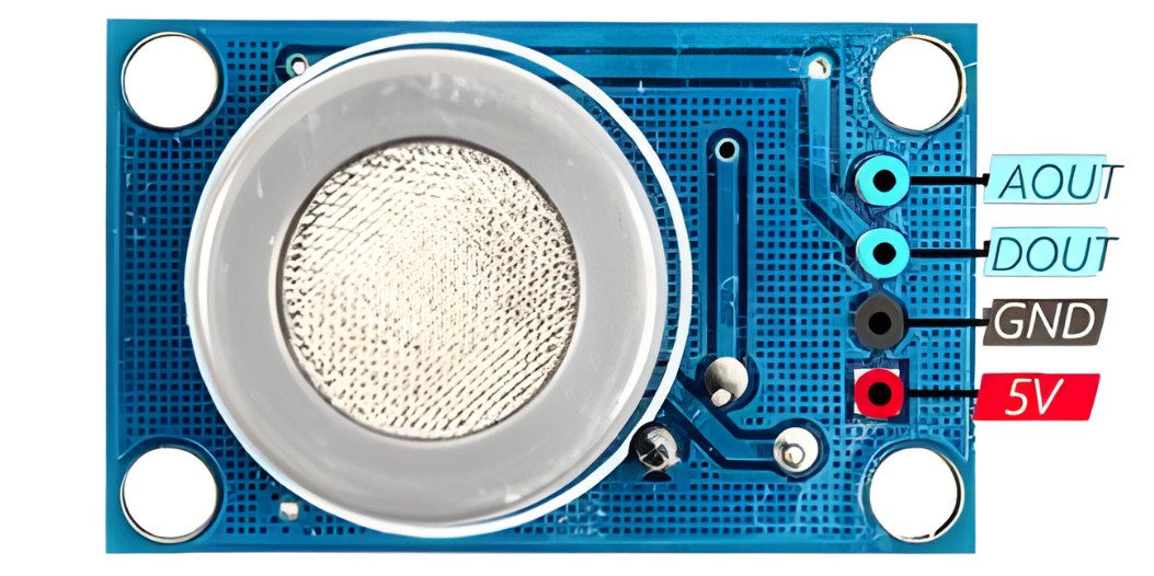
- VCC: Power supply (typically 5V).
- GND: Ground.
- AO (Analog Output): Provides analog signal.
- DO (Digital Output): Provides digital signal.
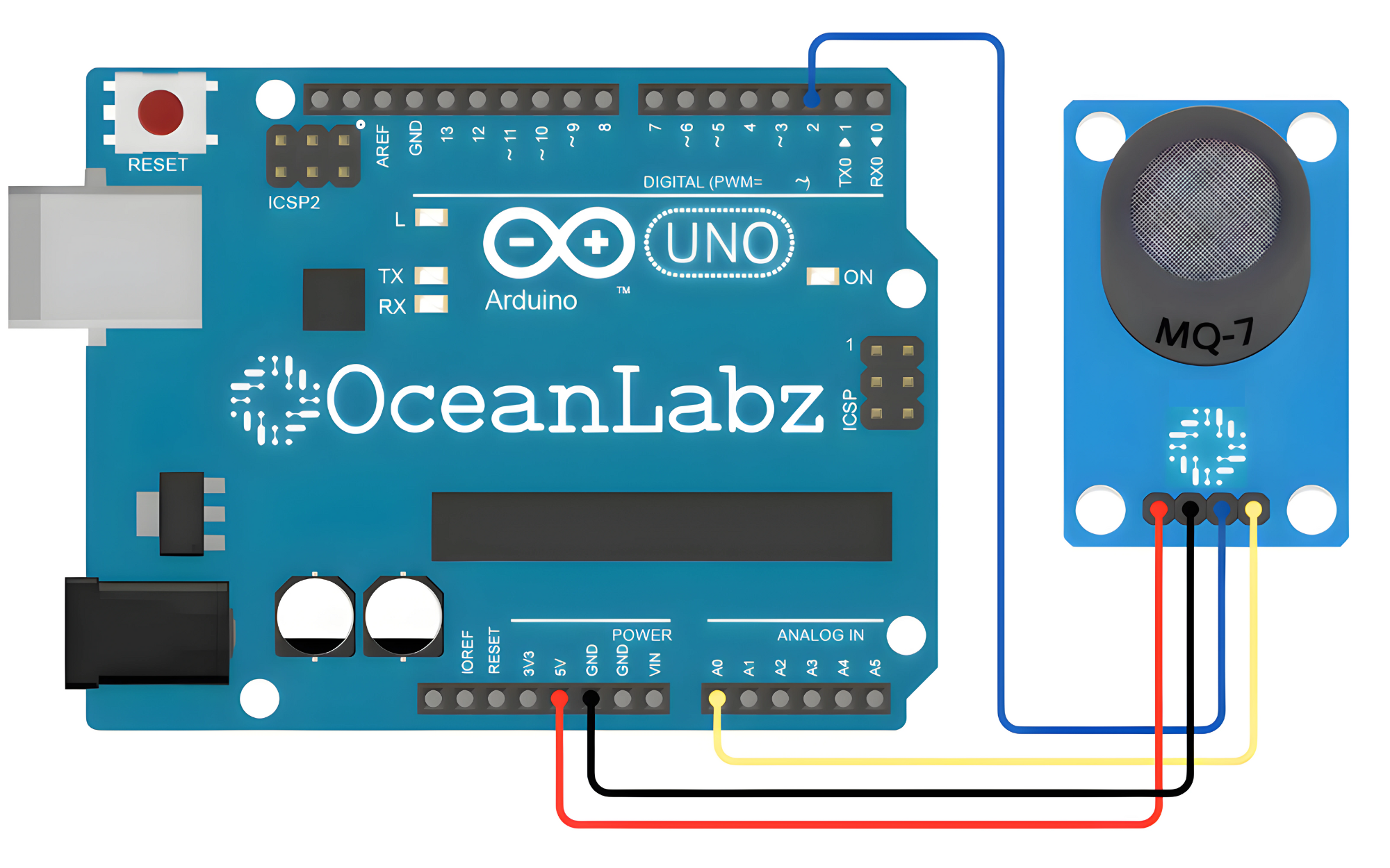
Circuit Diagram
| MQ-7 Pin | Arduino Pin |
| VCC | 3.3~5 V |
| GND | GND |
| AO | Analoge A0 |
| DO | Digital Pin 2 |
Programming With Arduino
Step 1: Open your first sketch
- Open the Arduino IDE.
- Copy and paste the provided code into a new sketch in the Arduino IDE:
// Define pin connections
const int analogPin = A0; // Analog output pin
const int digitalPin = 2; // Digital output pin

void setup() {
  // Initialize serial communication
  Serial.begin(9600);

  // Set digital pin as input
  pinMode(digitalPin, INPUT);
}

void loop() {
  // Read analog output
  int analogValue = analogRead(analogPin);

  // Read digital output
  int digitalValue = digitalRead(digitalPin);

  // Print sensor readings
  Serial.print("Analog Output: ");
  Serial.println(analogValue);
  Serial.print("Digital Output: ");
  Serial.println(digitalValue);

  // Wait for a short delay
  delay(1000);
}
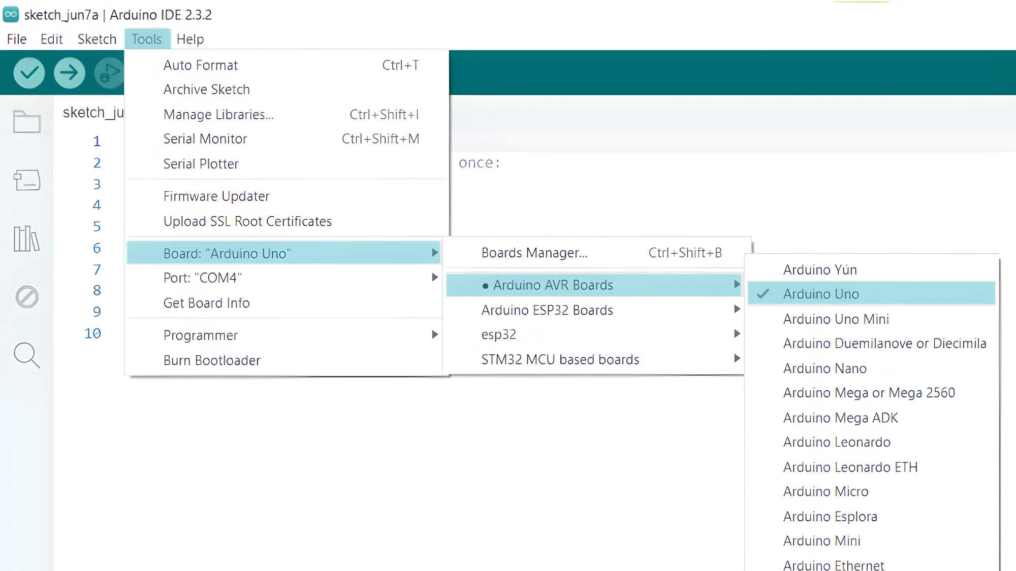
Step 2: Select your board type and port
- Go to Tools > Board and select your Arduino board (e.g., Arduino Uno).
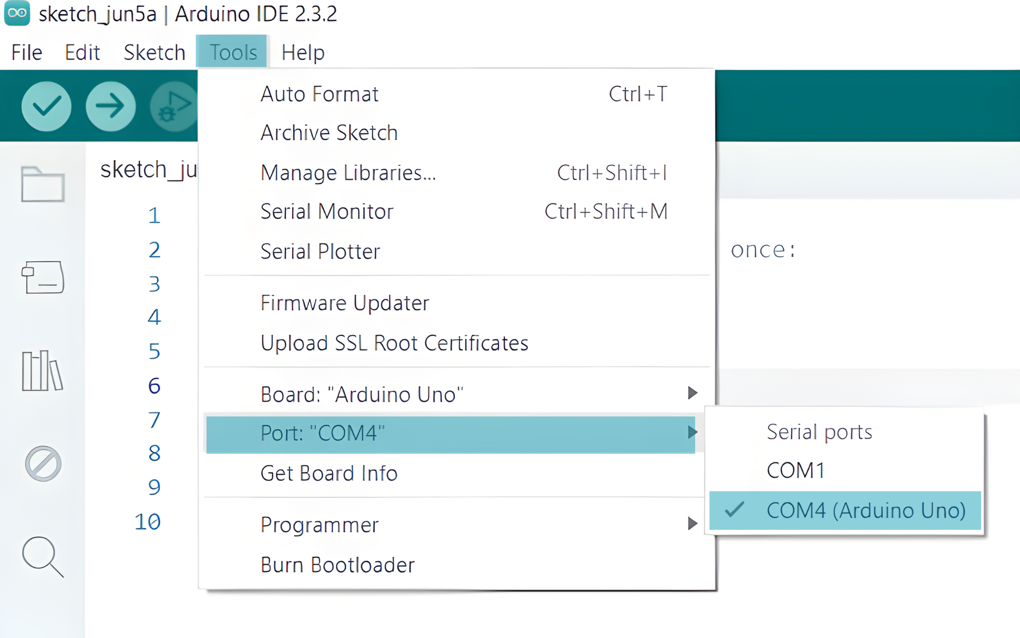
- Go to Tools > Port and select the port to which your Arduino is connected.
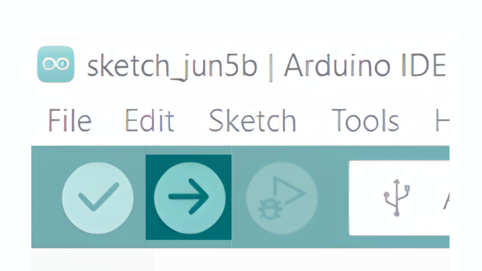
- Verify and upload the code to your Arduino board.
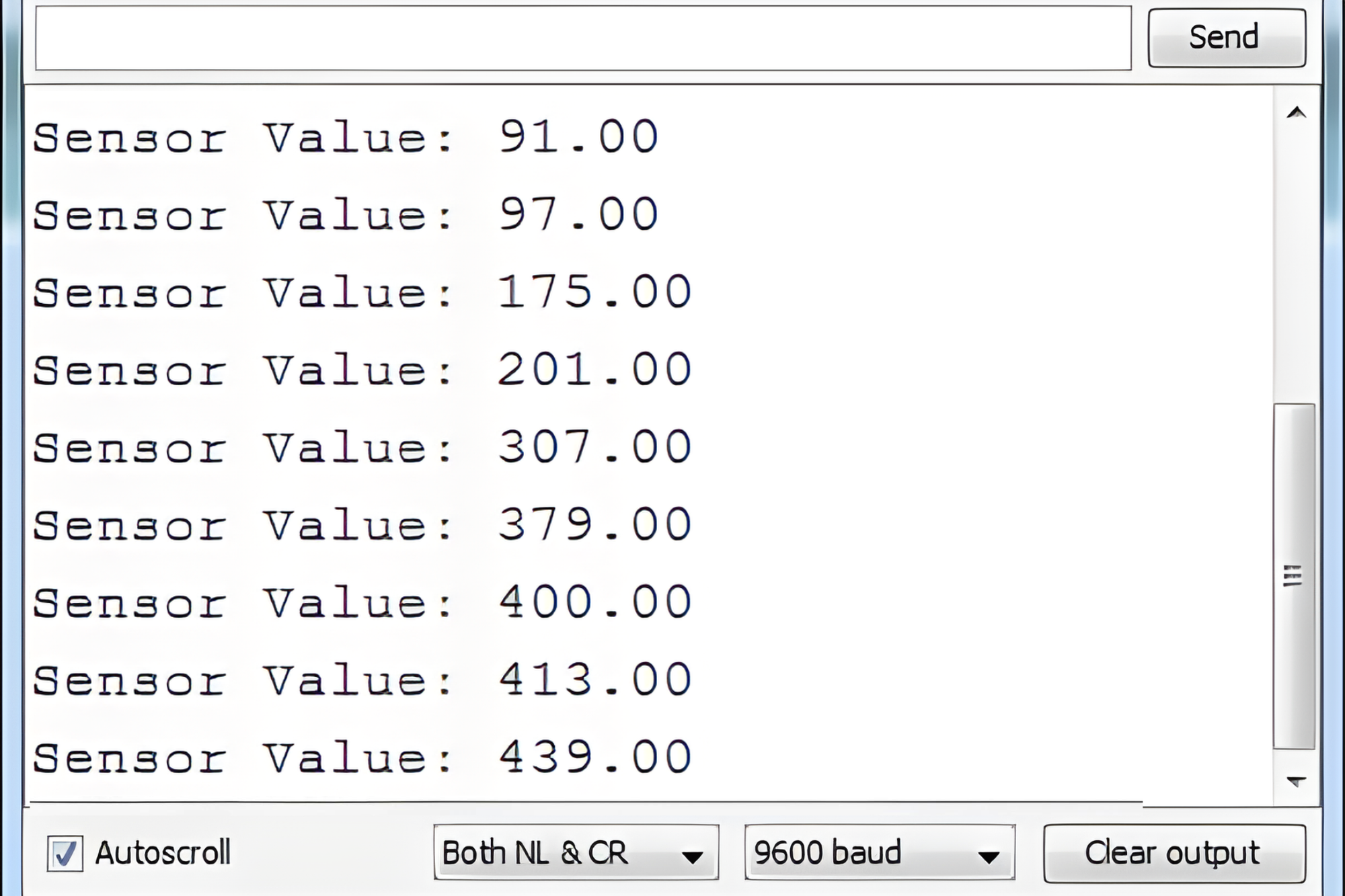
Step 3: Open Serial Monitor:
- Once the code is uploaded successfully, open the Serial Monitor in the Arduino IDE.
- Set the baud rate to 9600 baud.