Index
Introduction

The MQ2 gas sensor is a MOS (Metal Oxide Semiconductor) sensor that operates on 5V DC and consumes approximately 800mW. It is commonly used to detect the presence of gases such as LPG, Smoke, Alcohol, Propane, Hydrogen, Methane and Carbon Monoxide, with concentrations ranging from 200 to 10000 parts-per-million (ppm).
Parts-per-million is a unit of measurement commonly used to express gas concentration. In this context, 1 ppm means that for every million gas molecules, one molecule is of the gas being measured, and the remaining molecules are other gases. It’s important to note that while the MQ2 sensor can detect the presence of multiple gases, it cannot identify them. Therefore, it’s best used for measuring changes in the concentration of a known gas rather than detecting which gas is present.
Hardware Overview

Sensor: Made of tin dioxide (SnO2), the resistance of this layer changes in the presence of different gases. Higher gas concentrations decrease the resistance. The MQ-2 sensor includes a heating element that heats the sensor to a specific temperature to detect gases. The heating element ensures the sensor operates correctly and consistently.
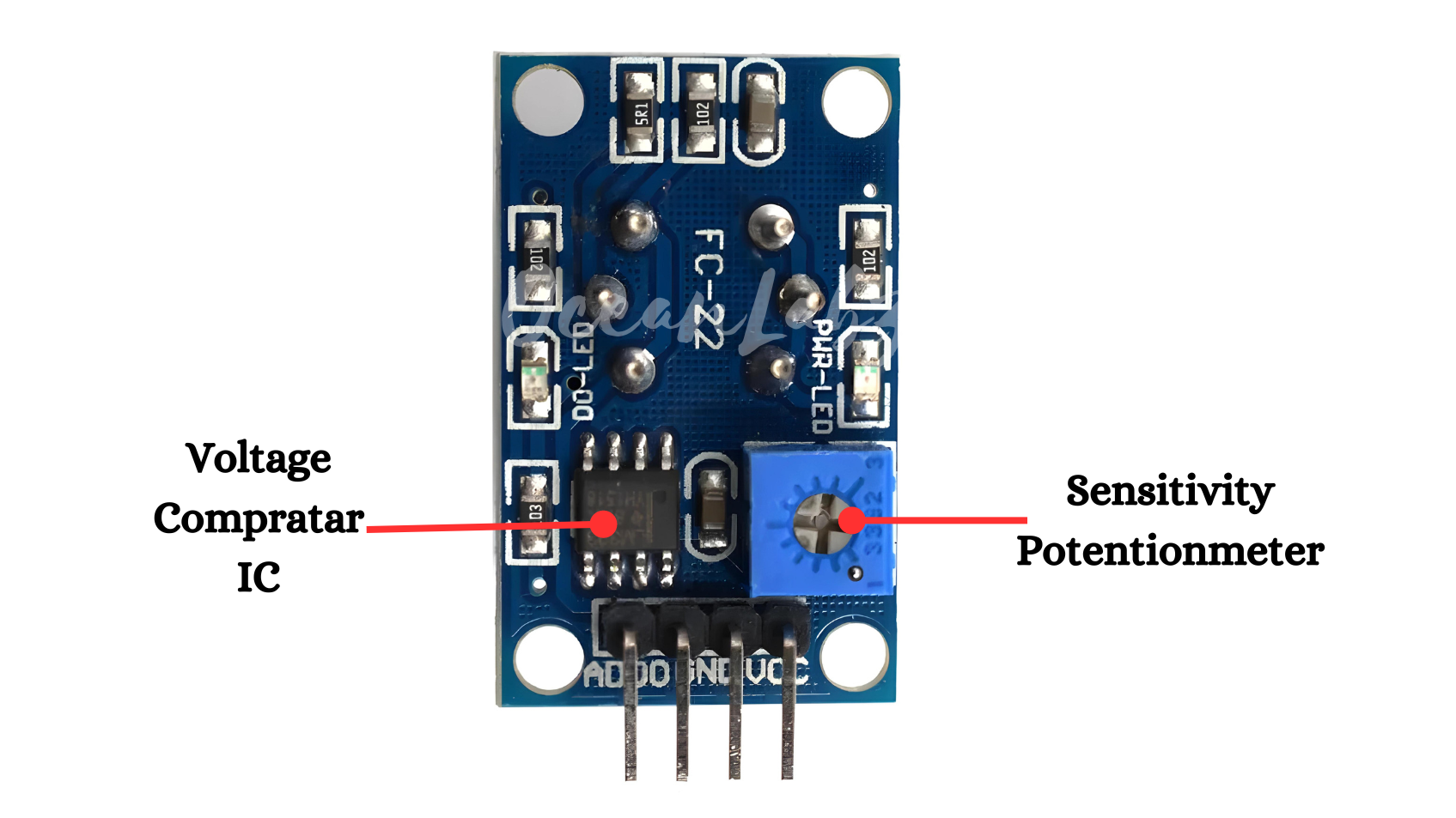
Potentiometer: An onboard potentiometer is used to set the threshold for the digital output. By adjusting this potentiometer, you can set the sensitivity of the sensor for digital output.
Voltage Comparator IC: The MQ-2 sensor module often includes a voltage comparator IC, such as the LM393, which is crucial for its digital output functionality.

Power LED: This LED indicates that the sensor module is powered. It usually lights up when the module is connected to a power source.
Status LED: This LED provides a visual indication of the sensor’s digital output. It lights up when the gas concentration exceeds the set threshold, corresponding to the digital output being high.
Working Principle
First of all we start with the general functionality of gas sensors. Inside the gas sensor is a chemiresistor that changes the resistance based on its sensing material. The following picture helps us to understand this functionality.

In most cases the sensing material is a tin dioxide (SnO2) material that has free electrons inside. These free electrons are attracted by the oxygen towards the surface of the sensing material (left side of the picture). On the surface, the oxygen is absorbed, due to the heated surface and therefore there are no free electrons in the tin dioxide. The result is: without free electrons there is no electrical current flow.
In an environment of toxic or combustible gases, the gas breaks the connection between the absorbed oxygen and the electrons. (right side of the picture) The released electrons are now free and back in their initial position, where they enable the current flow. How high the current flow is, depends on the amount of free electrons available in the SnO2 that is proportional with the concentration of toxic or combustible gases.
Due to Ohms law a higher current flow results in a higher potential difference, which is measured as output voltage on the analog output of the sensor, using a simple voltage divider network. Therefore the concentrations of gas can be measured.
The type of sensor is defined by the sensing material inside the sensor. Although some of the gas sensors are sensitive to multiple gases, the sensor can not identify which of the gases are in higher concentration.
Application
- Gas Leakage Detector
- Indoor Air Quality Monitoring
- Kitchen Safety System
Technical Specification
Here are some of the technical specifications of the MQ2 gas sensor:
- Operating voltage: 5V DC
- Power consumption: ~800mW
- Detection range: 200ppm to 10,000ppm of LPG, smoke, propane, hydrogen, methane, alcohol, and carbon monoxide gases.
- Sensitivity adjustment: via potentiometer on the module
- Analog output voltage range: 0V to 5V
- Digital output signal: TTL (5V) compatible, active low
- Warm-up time: approximately 1 minute
- Operating temperature: -10°C to 50°C
- Operating humidity: 95%RH or lower (non-condensing)
- Dimensions: 32mm x 22mm x 27mm
- Weight: 5 grams
Pinout

- VCC: This pin is connected to the positive terminal of the power supply (5V DC).
- GND: This pin is connected to the negative terminal of the power supply (GND).
- AO (Analog Output): Provides a continuous analog signal proportional to the gas concentration.
- DO (Digital Output): Provides a high or low digital signal depending on the gas concentration relative to a set threshold.
Circuit Diagram
| MQ2 Pin | ARDUINO Pin |
| VCC | 5 V |
| GND | GND |
| A0 | Analog A0 |

Programming With Arduino
Step 1: Open your first sketch
- Open the Arduino IDE.
- Copy and paste the provided code into a new sketch in the Arduino IDE:
// Define the analog pin connected to the MQ-2 sensor
const int mq2Pin = A0; // Analog pin A0 for MQ-2 sensor output

void setup() {
  Serial.begin(9600); // Initialize serial communication
}

void loop() {
  int sensorValue = analogRead(mq2Pin); // Read analog value from MQ-2 sensor
  float voltage = sensorValue * (5.0 / 1023.0); // Convert analog value to voltage (0-5V)

  // Calculate gas concentration using a calibration curve
  float ppm = MQ2_getPPM(voltage);

  // Print gas concentration to the Serial Monitor
  Serial.print("Gas Concentration (PPM): ");
  Serial.println(ppm);

  delay(1000); // Delay before taking the next reading
}

// Function to calculate gas concentration (PPM) based on MQ-2 sensor output
float MQ2_getPPM(float voltage) {
  // Calibration curve parameters (adjust based on your sensor and gas)
  float RS_air = 10.0; // Sensor resistance in clean air (in kilo ohms)
  float RL = 2.0; // Load resistance (in kilo ohms)
  float ratio = RL / RS_air; // Ratio of RL to RS_air

  // Calculate sensor resistance (RS) in kilo ohms
  float RS = ((5.0 / voltage) - 1.0) * RL;

  // Calculate gas concentration (PPM) using the derived formula (adjust based on calibration)
  float ppm = 1000.0 * pow((RS / RS_air), ratio); // Gas concentration in parts per million (PPM)

  return ppm;
}
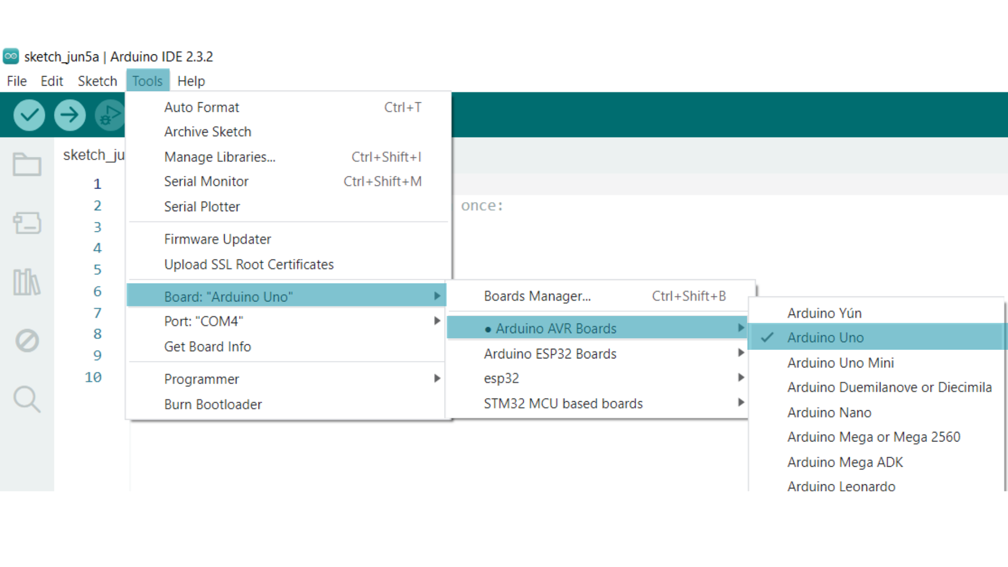
Step 2: Select your board type and port
You’ll need to select the entry in the Tools > Board menu that corresponds to your Arduino board.
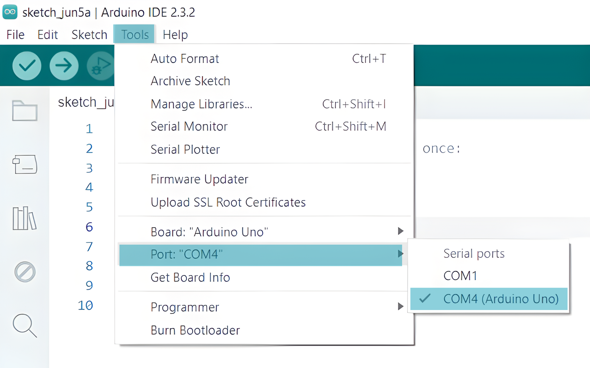
Select the serial device of the board from the Tools | Serial Port menu. This is likely to be COM3 or higher (COM1 and COM2 are usually reserved for hardware serial ports). To find out, you can disconnect your board and re-open the menu; the entry that disappears should be the Arduino board. Reconnect the board and select that serial port.
Step 3: Upload the Sketch
- Click the “Upload” button (right arrow icon) to upload the sketch to the Arduino.

NOTE : It’s important to note that the MQ2 gas sensor is not intended for precise measurement of gas concentrations and is primarily used for detecting the presence of gases in the air. The sensitivity and accuracy of the sensor may vary depending on the environmental conditions and the specific gas being detected.
Step 4: Testing
Monitor the Serial Monitor output to see gas concentrations in PPM and check for sensor accuracy and response time.