Index

Introduction
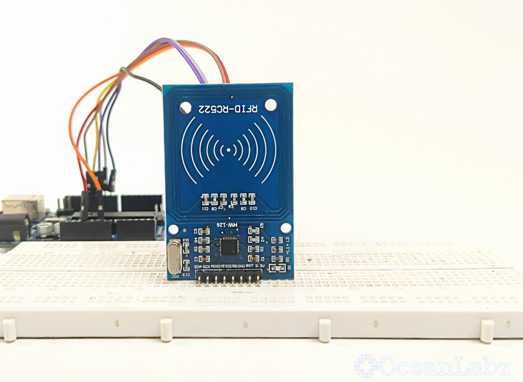
The MFRC522 RFID module is a popular RFID reader module used with Arduino to read RFID tags. It communicates via SPI, enabling quick data exchange and making it suitable for security and access control projects. Here’s a guide on setting up the MFRC522 RFID module with Arduino and reading RFID tag data.
Required Components
- Arduino Board (e.g., Arduino Uno)
- MFRC522 RFID module, RFID tags
- Jumper Wires
- Breadboard (optional)
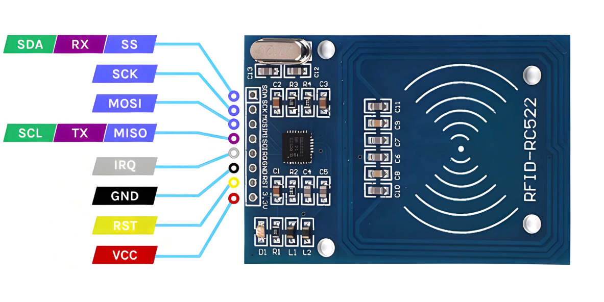
Pinout

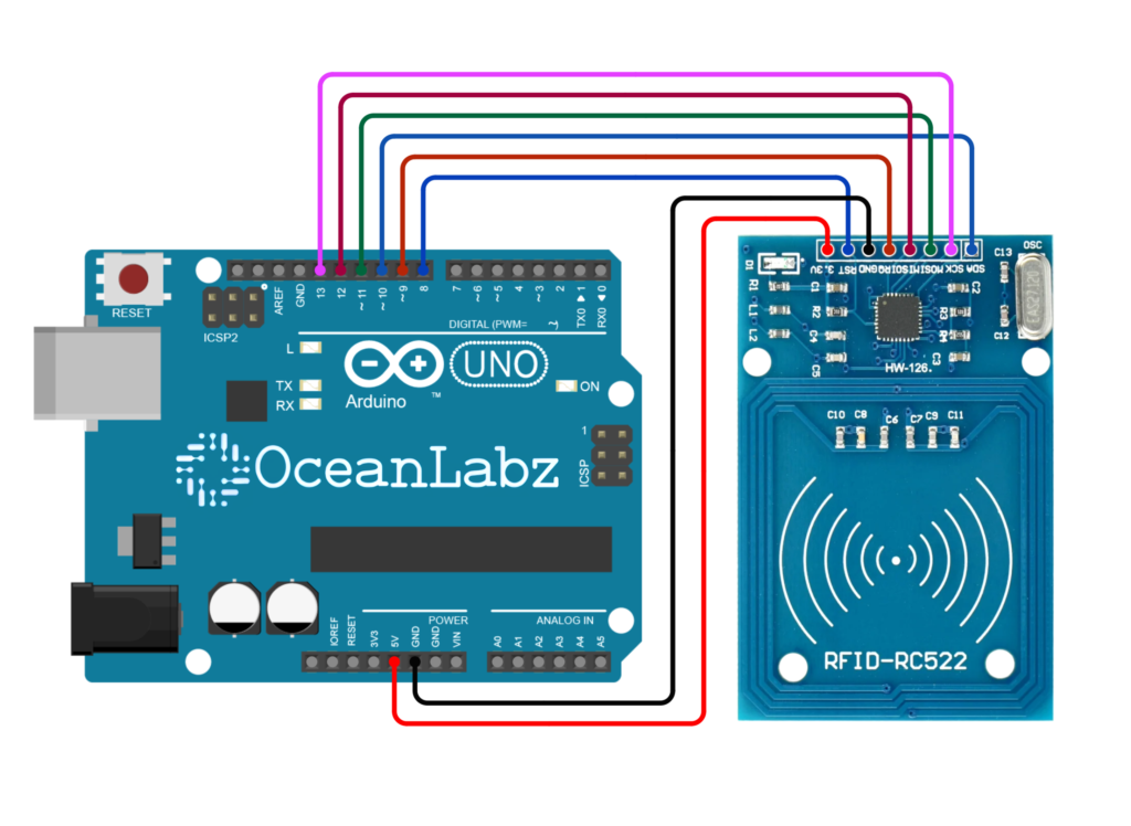
Circuit Diagram / Wiring
- RFID SENSOR VCC → 5V (Arduino)
- RFID SENSOR GND → GND (Arduino)
- RFID SENSOR SDA → Pin D10 (Arduino)
- RFID SENSOR SCK → Pin D13 (Arduino)
- RFID SENSOR MOSI → Pin D11 (Arduino)
- RFID SENSOR MISO → Pin D12 (Arduino)
- RFID SENSOR IRQ → Pin D9 (Arduino)
- RFID SENSOR RST → Pin D8 (Arduino)

Programming With Arduino
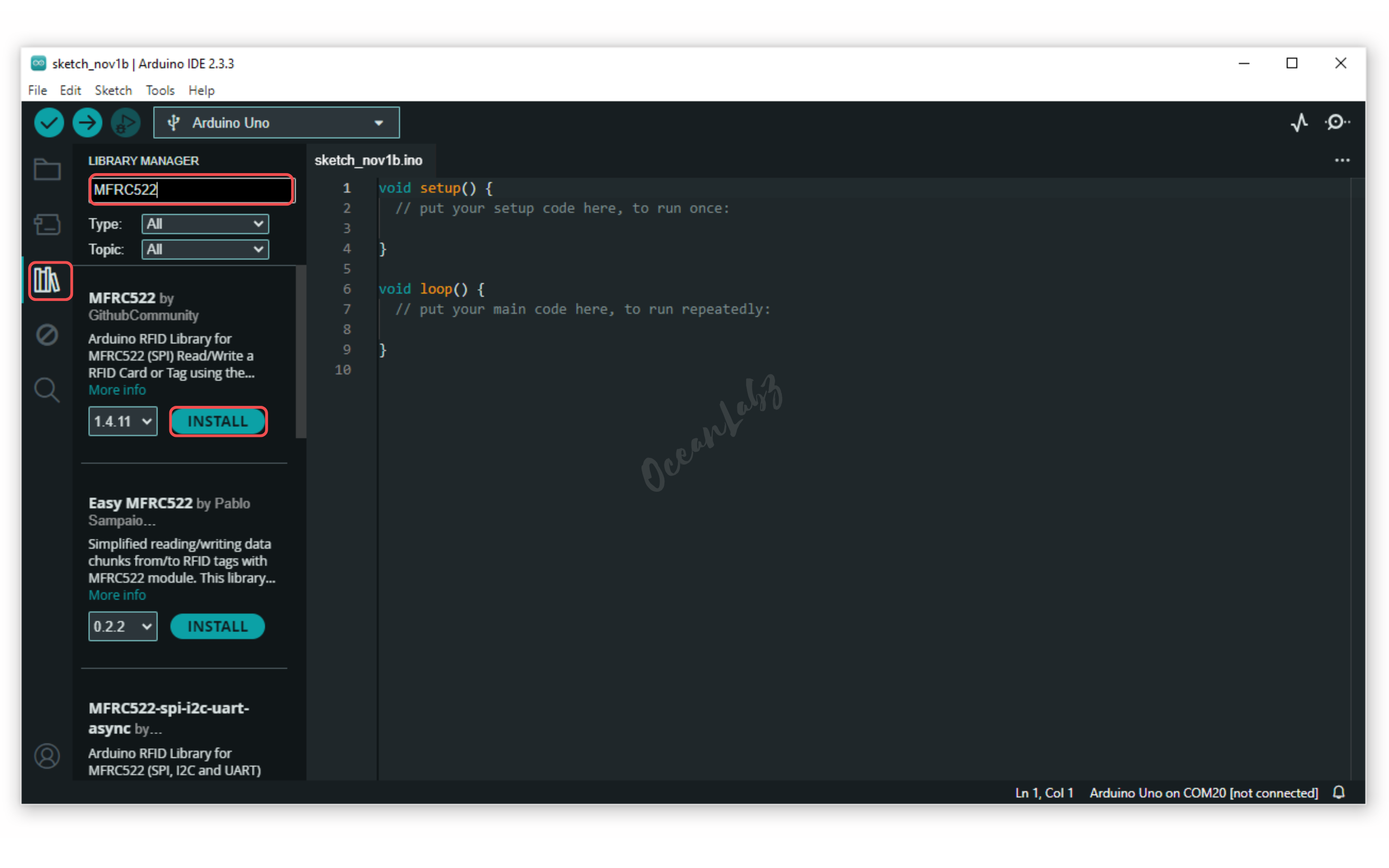
- Go to the “Libraries” tab on the left-hand side of the screen.
- Click on the “Library Manager” button (book icon) at the top of the Libraries tab.
- In the Library Manager window, type “MFRC522” in the search bar, locate the MFRC522 library, and click on the “Install” button next to it.

- Copy and paste the provided code into a new sketch in the Arduino IDE:
#include <SPI.h>
#include <MFRC522.h>

#define RST_PIN 8
#define SS_PIN 10

MFRC522 mfrc522(SS_PIN, RST_PIN); // Create MFRC522 instance

// Define UIDs for object 1 and object 2
byte object1UID[] = {0x83, 0x4D, 0x4C, 0xC5}; // UID of object 1
byte object2UID[] = {0xE5, 0xF6, 0x07, 0x08}; // UID of object 2 (change as needed)

void setup() {
  Serial.begin(9600); // Initialize serial communications with the PC
  while (!Serial); // Do nothing if no serial port is opened
  SPI.begin(); // Init SPI bus
  mfrc522.PCD_Init(); // Init MFRC522
  delay(4); // Optional delay
  Serial.println(F("Scan PICC to see UID..."));
}

void loop() {
  // Reset the loop if no new card present on the sensor/reader.
  if (!mfrc522.PICC_IsNewCardPresent()) {
    return;
  }

  // Select one of the cards
  if (!mfrc522.PICC_ReadCardSerial()) {
    return;
  }

  // Print the detected UID in a readable format
  Serial.print("Card UID: ");
  for (byte i = 0; i < mfrc522.uid.size; i++) {
      Serial.print(mfrc522.uid.uidByte[i], HEX);
      if (i < mfrc522.uid.size - 1) {
          Serial.print(" ");
      }
  }
  Serial.println(); // New line after printing UID

  // Check the UID of the scanned card
  if (compareUID(mfrc522.uid.uidByte, object1UID)) {
    Serial.println("Object 1 detected!");
  }
  else if (compareUID(mfrc522.uid.uidByte, object2UID)) {
    Serial.println("Object 2 detected!");
  }
  else {
    Serial.println("Unknown object detected!");
  }

  // Halt the PICC
  mfrc522.PICC_HaltA();
}

// Function to compare two UIDs
bool compareUID(byte *uid1, byte *uid2) {
  for (byte i = 0; i < 4; i++) { // Adjust the number of bytes based on your UID length
    if (uid1[i] != uid2[i]) {
      return false;
    }
  }
  return true;
}
Explanation
- The code uses the MFRC522 library to interface with an RFID reader.
- It defines two unique UIDs for two different RFID cards to detect them.
- In the
setup()function, it initializes the Serial Monitor and the RFID reader. - The
loop()function checks for new cards, reads their UIDs, and compares them with predefined UIDs. - Depending on the detected UID, it prints messages indicating which object is detected or if an unknown object is scanned.
Testing and Troubleshooting
- Ensure the connections (SDA, SCK, MOSI, MISO, RST, and GND) between the MFRC522 module and Arduino are secure and correctly configured.
- Verify that the power supply is adequate; the MFRC522 should be powered with 3.3V, not 5V, to avoid damage.
- If the module does not respond, check the SPI library installation in your Arduino IDE and ensure the correct board is selected.
- Use the Serial Monitor to check for any error messages or debugging information that can help identify issues during the scanning process.
Arduino Projects:
Arduino Project 1 – Smart Access Control System with RFID, Servo, and OLED Display
This project is a Smart Access Control System using RFID technology for secure authentication. When an authorized RFID tag is scanned, a servo motor unlocks, LEDs indicate access status, and an OLED display shows real-time messages. A buzzer provides audio feedback for successful or denied access, ensuring a user-friendly and secure experience.
Required Components
- Arduino Board (e.g., Arduino Uno)
- MFRC522 RFID module, RFID tags
- Servo Motor
- OLED Display
- Buzzer Module
- Tow LEDs (Green,Red)
- Jumper Wires
- Breadboard
Circuit Diagram / Wiring
- RFID
- RFID SENSOR 3.3V → 3.3V (Arduino)
- RFID SENSOR GND → GND (Arduino)
- RFID SENSOR SDA → Pin D10 (Arduino)
- RFID SENSOR SCK → Pin D13 (Arduino)
- RFID SENSOR MOSI → Pin D11 (Arduino)
- RFID SENSOR MISO → Pin D12 (Arduino)
- RFID SENSOR RST → Pin D9 (Arduino)
- Servo Motor
- Servo (RED) VCC → 5V (Arduino)
- Servo (BROWN) GND → GND (Arduino)
- Servo (ORENG) PWM → Pin D6 (Arduino)
- OLED Display
- OLED VCC → 5V (Arduino)
- OLED GND → GND (Arduino)
- OLED SDA → Pin A4 (Arduino)
- OLED SCK → Pin A5 (Arduino)
- Buzzer Module
- Buzzer VCC → 5V (Arduino)
- Buzzer GND → GND (Arduino)
- Buzzer SINGNAL → Pin D8 (Arduino)
- LEDs
- Connect the red LED anode to pin 4 (via a 220-ohm resistor) and cathode to GND.
- Connect the green LED anode to pin 3 (via a 220-ohm resistor) and cathode to GND.

Arduino Code
Make sure you have the required libraries installed:
- MFRC522 library for RFID.
- Servo library for Servo motor
- Adafruit_GFX and Adafruit_SSD1306 for OLED.
#include <SPI.h>
#include <MFRC522.h>
#include <Adafruit_GFX.h>
#include <Adafruit_SSD1306.h>
#include <Servo.h>

// Pin definitions
const int buzzerPin = 8;
#define RST_PIN 9        // Reset pin for RFID
#define SS_PIN 10        // Slave Select pin for RFID
#define GREEN_LED 3      // Green LED pin
#define RED_LED 4        // Red LED pin
#define SERVO_PIN 6      // Servo motor pin
#define SCREEN_ADDRESS 0x3C  // I2C address for the display

// OLED display setup
#define SCREEN_WIDTH 128
#define SCREEN_HEIGHT 64
Adafruit_SSD1306 display(SCREEN_WIDTH, SCREEN_HEIGHT, &Wire);

// RFID setup
MFRC522 rfid(SS_PIN, RST_PIN);
MFRC522::MIFARE_Key key;

// Servo setup
Servo myServo;

// Authorized UID (replace with your card/tag UID)
byte authorizedUID[] = {0x83, 0x4D, 0x4C, 0xC5};

void setup() {
  Serial.begin(9600);  // Initialize serial communication for debugging

  // Initialize RFID module
  SPI.begin();
  rfid.PCD_Init();

  // Initialize OLED display
  if (!display.begin(SSD1306_SWITCHCAPVCC, SCREEN_ADDRESS)) {
    Serial.println(F("SSD1306 allocation failed"));
    for (;;); // Halt execution
  }

  display.clearDisplay();
  display.setTextSize(2);
  display.setTextColor(SSD1306_WHITE);

  // Initialize components
  pinMode(GREEN_LED, OUTPUT);
  pinMode(RED_LED, OUTPUT);
  pinMode(buzzerPin, OUTPUT);
  myServo.attach(SERVO_PIN);
  myServo.write(0); // Lock position

  // Display welcome message
  displayMessage("RFID\      System\nReady\ for\ Scan..");
}

void loop() {
  // Check for RFID card/tag
  if (!rfid.PICC_IsNewCardPresent() || !rfid.PICC_ReadCardSerial()) {
    return;
  }

  // Read the UID
  byte readUID[4];
  for (byte i = 0; i < 4; i++) {
    readUID[i] = rfid.uid.uidByte[i];
  }

  // Print UID to Serial Monitor for debugging
  Serial.print("UID: ");
  for (byte i = 0; i < 4; i++) {
    Serial.print(readUID[i], HEX);
    Serial.print(" ");
  }
  Serial.println();  // Print a newline for better readability

  // Compare UID with authorized UID
  if (isAuthorized(readUID)) {
    grantAccess();
  } else {
    denyAccess();
  }

  // Halt PICC (tag/card) to prevent repeated reads
  rfid.PICC_HaltA();
}

bool isAuthorized(byte *uid) {
  for (byte i = 0; i < 4; i++) {
    if (uid[i] != authorizedUID[i]) {
      return false;
    }
  }
  return true;
}

void grantAccess() {
  digitalWrite(GREEN_LED, HIGH);
  digitalWrite(RED_LED, LOW);
  tone(buzzerPin, 1500);
  delay(200);
  noTone(buzzerPin);

  displayMessage("  Access    Granted\   Welcome!");
  myServo.write(90); // Unlock position
  delay(3000);       // Keep unlocked for 3 seconds
  myServo.write(0);  // Lock position

  digitalWrite(GREEN_LED, LOW);
}

void denyAccess() {
  digitalWrite(RED_LED, HIGH);
  digitalWrite(GREEN_LED, LOW);
  for (int i = 0; i < 3; i++) {
    tone(buzzerPin, 1500, 500);
    delay(100);
    noTone(buzzerPin);
    delay(100);
  }

  displayMessage("  Access    Denied\    Invalid    Card!");
  digitalWrite(RED_LED, LOW);
}

void displayMessage(String message) {
  display.clearDisplay();
  display.setCursor(0, 0);
  display.println(message);
  display.display();
}
Steps to Use:
Scan the New Card:
Upload the code to your Arduino. When you bring a new card close to the RFID reader, the UID of the card will be printed in the Serial Monitor.
- Open the Serial Monitor in the Arduino IDE (set baud rate to 9600).
- Note down the UID printed, e.g.,
UID: 83 4D 4C C5.
Update the Authorized UID in Code:
Replace the current authorizedUID array with the new card’s UID. For example:
byte authorizedUID[] = {0x83, 0x4D, 0x4C, 0xC5}; // Replace with your new UID
Re-upload the Code:
After replacing the UID, save the code and upload it back to the Arduino.
Test with the New Card:
Bring the new card close to the RFID reader to confirm that access is granted.
Example:
If the new card’s UID is A1 B2 C3 D4, update the code like this:
byte authorizedUID[] = {0xA1, 0xB2, 0xC3, 0xD4};
Explanation
- If the card matches, it grants access by unlocking a servo (90°), lighting the green LED, and showing “Access Granted” on an OLED display.
- If the card doesn’t match, it denies access by beeping, lighting the red LED, and showing “Access Denied.”
- The card’s UID is printed to the Serial Monitor for debugging or finding new card UIDs.
- An OLED display is used to show system status messages like “Ready for Scan.”
- The system locks the servo again after 3 seconds and resets for the next scan.
Troubleshooting
- RFID Scanning Issues: Verify wiring and library setup; ensure tags are functional and authorized in the code.
- Servo Not Moving: Check power supply and connections; use an external source if needed for sufficient current.
- OLED Display Blank: Confirm I2C connections, correct I2C address in the code, and secure wiring.
- LEDs or Buzzer Not Working: Double-check pin assignments in the code and test components independently.
- System Unresponsive: Ensure all modules are powered properly and test each component separately to isolate issues.


