Index
Introduction
The OLED (Organic Light-Emitting Diode) 1306 is a compact and versatile display module that uses OLED technology to generate bright and vivid images without requiring a backlight. The 1306 model typically refers to a 0.96-inch OLED display with 128×64 pixel resolution
Working Principle
The OLED 1306 display works by emitting light from organic compounds (such as carbon-based molecules) when an electric current is passed through them. Unlike LCD displays that require a backlight, OLED displays emit light directly, resulting in higher contrast and energy efficiency.
Each pixel in the OLED display can be controlled individually, allowing for detailed graphics and text rendering. The display communicates with a microcontroller (such as Arduino or Raspberry Pi) using the I2C protocol, which simplifies the interfacing process and reduces the number of required connection pins.
OLED Memory Map
To control the display effectively, it’s essential to comprehend the memory map of the OLED display.
No matter the size of the OLED display, the SSD1306 driver features a 1KB Graphic Display Data RAM (GDDRAM) that holds the bit patterns for the screen. This 1KB memory is organized into 8 pages (numbered 0 to 7), each with 128 columns/segments (blocks 0 to 127). Each column can store 8 bits of data (bits 0 to 7). This clearly indicates that we have:
- 8 pages x 128 segments x 8 bits of data = 8192 bits = 1024 bytes = 1KB memory
The full 1KB memory, encompassing pages, segments, and data, is detailed below.
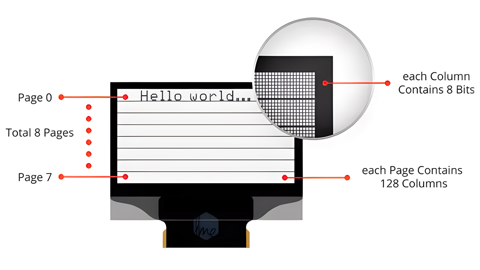
Each bit corresponds to a single OLED pixel on the screen, which can be turned ON or OFF through programming.
Application
- Embedded Systems: Displaying sensor data and status information in microcontroller-based projects.
- Wearable Devices: Showing notifications and health metrics on smartwatches and fitness trackers.
- DIY Electronics: Providing compact and low-power display solutions for hobbyist projects.
- Information Displays: Presenting time, weather, and other data in clocks and weather stations.
- Prototyping: Creating graphical interfaces for testing and development purposes.
- Education: Teaching microcontroller programming and display technology in educational projects.
- Consumer Electronics: Integrating into various consumer products for displaying settings and feedback.
Technical Specification
- Display Type: OLED (Organic Light-Emitting Diode)
- Resolution: 128×64 pixels
- Color: Monochrome (typically white or blue pixels on black background)
- Interface: I2C (Inter-Integrated Circuit) for communication
- Operating Voltage: Typically supports 3.3V to 5V
- Pixel Size: 0.96 inches
- Viewing Angle: Wide viewing angle with high contrast
- Power Consumption: Low power consumption compared to traditional LCD displays
- Dimensions: Compact size suitable for small electronic devices
Pinout
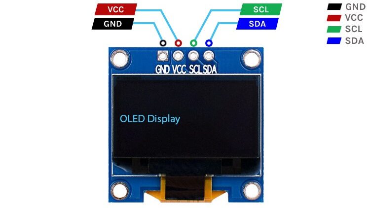
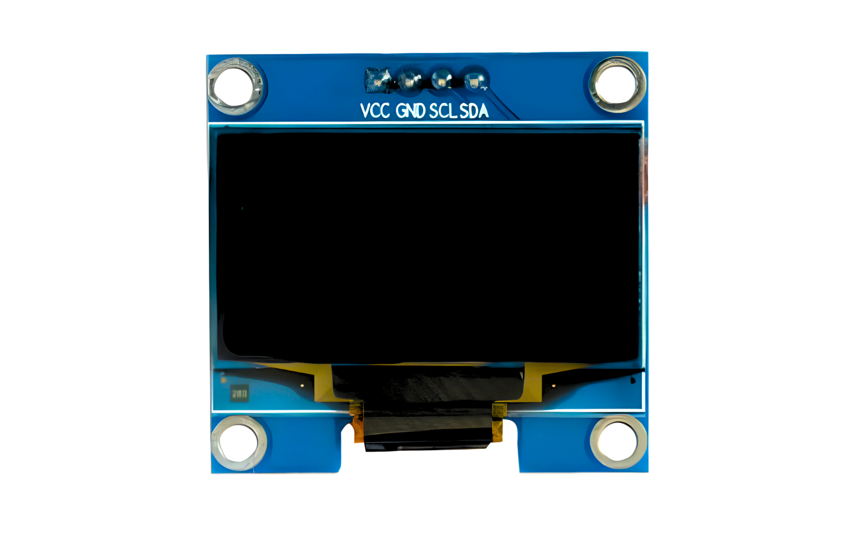
- GND: Ground pin
- VCC: Power supply pin (3.3V to 5V)
- SCL: Serial Clock pin for I2C communication
- SDA: Serial Data pin for I2C communication
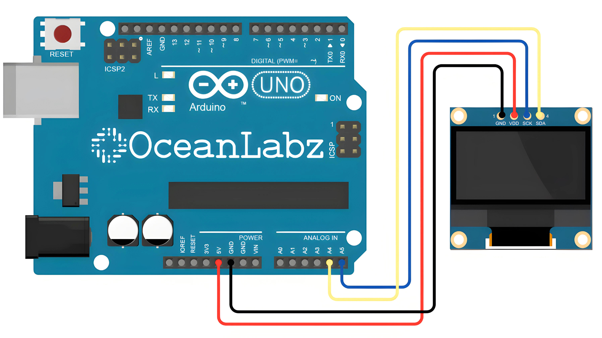
Circuit Diagram
| OLED Pin | Arduino Pin |
| VCC | 5 V |
| GND | GND |
| SDA | Analog A4 |
| SCL | Analog A5 |
Programming the OLED
Step 1: Install the Necessary Libraries
- Open the Arduino IDE.
- Install the Adafruit SSD1306 Library:
- Go to Sketch > Include Library > Manage Libraries.
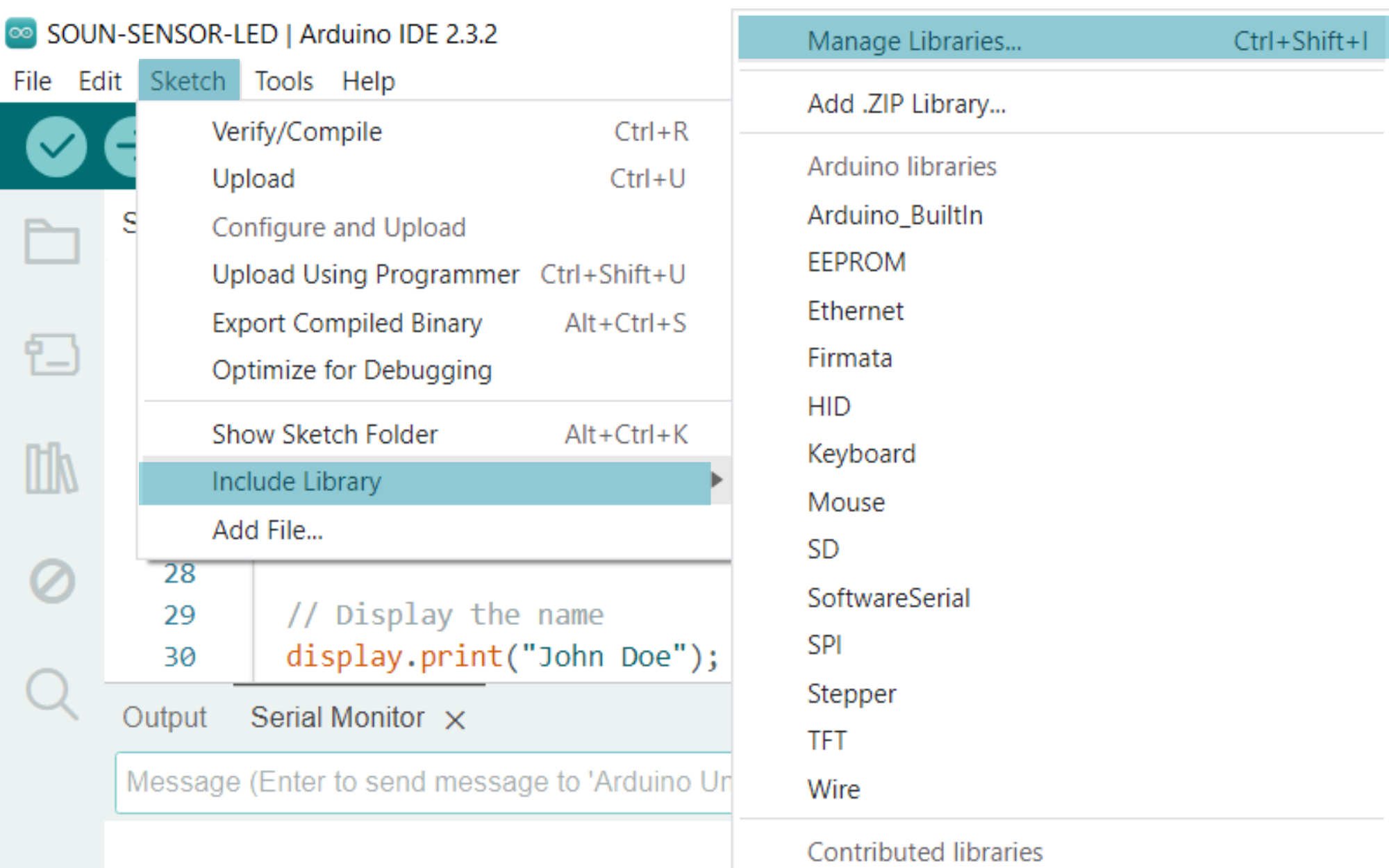
- In the Library Manager, type
Adafruit SSD1306in the search box. - Find
Adafruit SSD1306by Adafruit and click Install. - In the same Library Manager, type
Adafruit GFXin the search box. - Find
Adafruit GFX Libraryby Adafruit and click Install.

Step 2: Upload the Sketch
- Connect your Arduino to your computer using a USB cable.
- Open the Arduino IDE.
- Copy and paste the provided code into a new sketch in the Arduino IDE:
#include <Wire.h>
#include <Adafruit_GFX.h>
#include <Adafruit_SSD1306.h>

// Define the OLED display width and height
#define SCREEN_WIDTH 128
#define SCREEN_HEIGHT 64

// Create an instance of the SSD1306 display
Adafruit_SSD1306 display(SCREEN_WIDTH, SCREEN_HEIGHT, &Wire, -1);

void setup() {
  // Initialize the display with the I2C address 0x3C
  if(!display.begin(SSD1306_SWITCHCAPVCC, 0x3C)) {
    Serial.println(F("SSD1306 allocation failed"));
    for(;;);
  }

  // Clear the display buffer
  display.clearDisplay();

  // Set text size and color
  display.setTextSize(2);
  display.setTextColor(SSD1306_WHITE);

  // Set cursor position (x, y)
  display.setCursor(0, 20);

  // Display the name
  display.print(" OceanLabz");

  // Update the display to show the changes
  display.display();
}

void loop() {
  // Nothing to do here
}
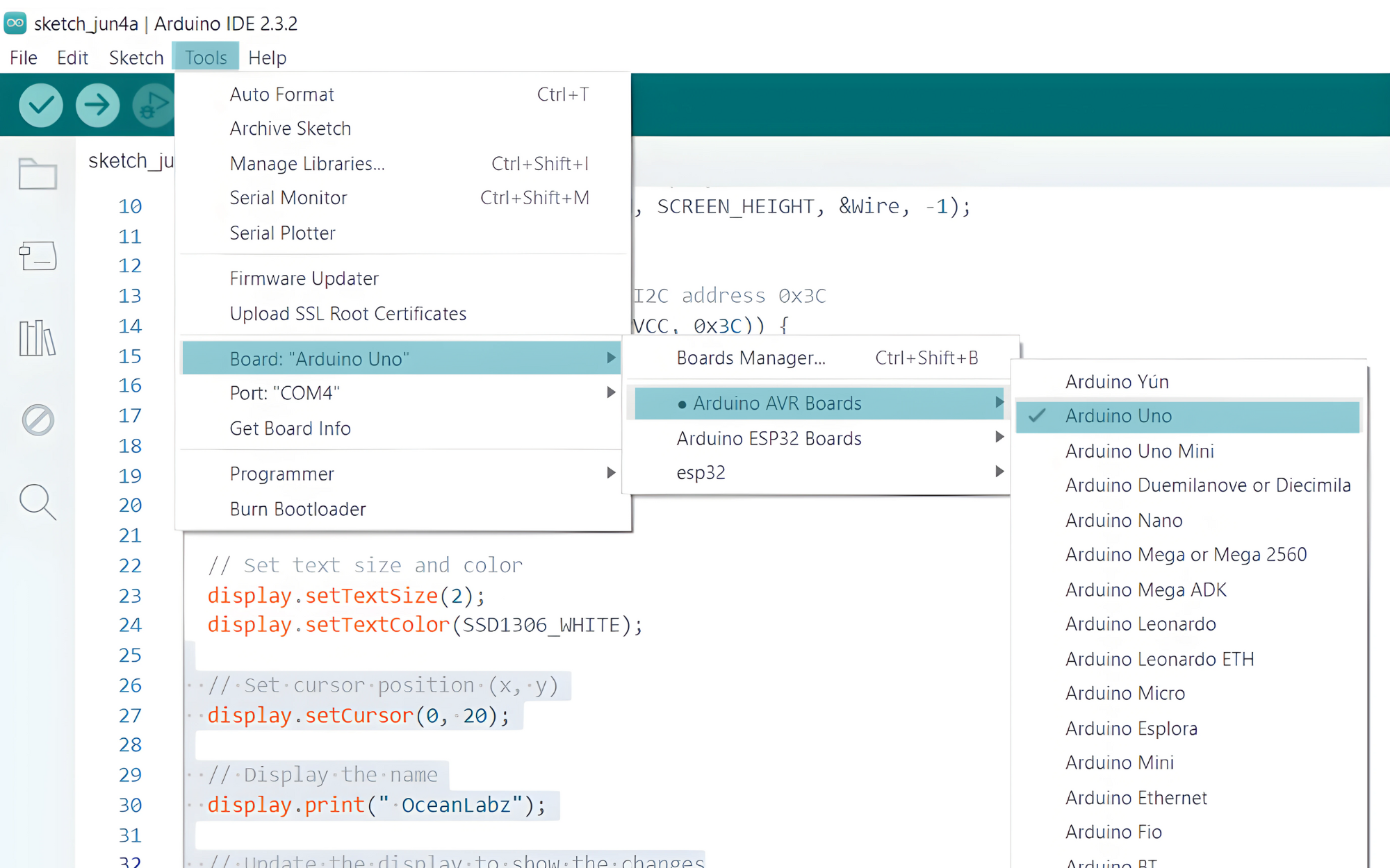
Step 3: Select the appropriate board and port
- Go to Tools > Board and select your Arduino board (e.g., Arduino Uno).
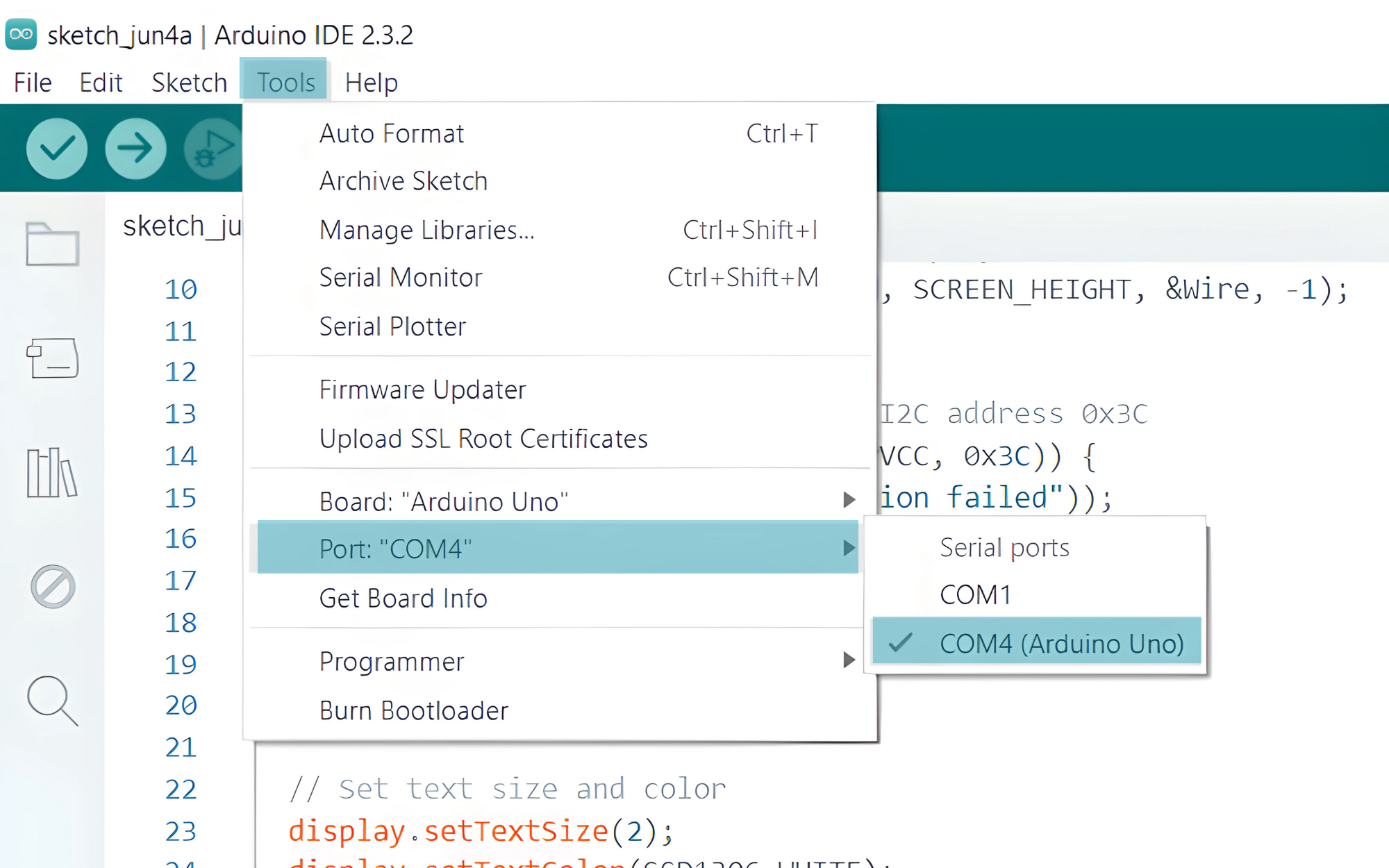
- Go to Tools > Port and select the port to which your Arduino is connected.
Step 4: Verify the Output
Once the upload is complete, the OLED display should show the text “OceanLabz”. If you encounter any issues, make sure the connections are correct and that the OLED display is powered properly. If the display does not initialize, check the I2C address (0x3C in the code) and ensure it matches the address of your OLED display.