Index

Introduction
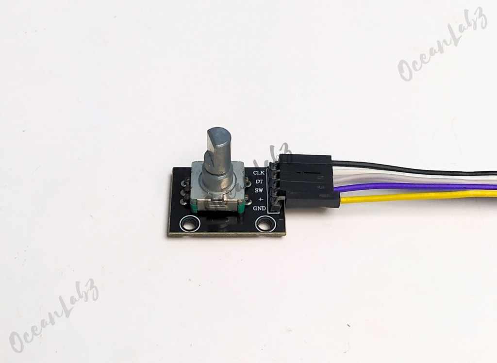
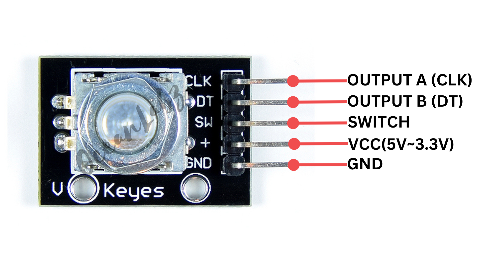
This project uses a rotary encoder with an Arduino to detect rotational movement and control a counter based on the direction of rotation. The encoder consists of three main pins: CLK (clock), DT (data), and SW (switch). By rotating the encoder, the position count increases or decreases, and the value is displayed on the Serial Monitor. Additionally, the switch pin can be used to detect button presses. This project demonstrates the functionality of a rotary encoder for interactive control applications.
Required Components
- Arduino UNO, Nano
- Rotary encoder (e.g., KY-040)
- Breadboard
- Jumper wires
Pinout

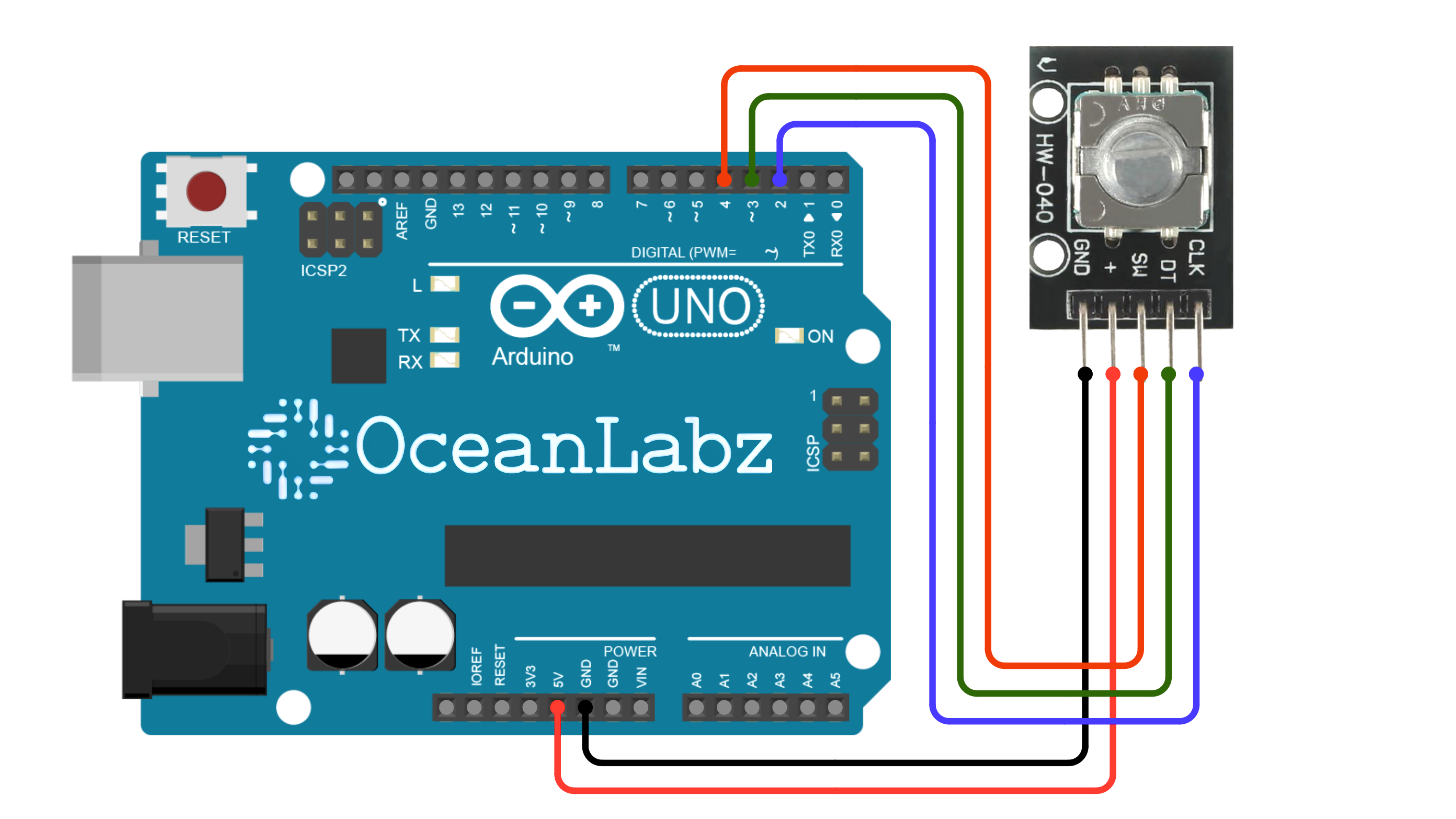
Circuit Diagram / Wiring
- ROTARY VCC → 5V (Arduino)
- ROTARY GND → GND (Arduino)
- ROTARY CLK → Pin D2 (Arduino)
- ROTARY DT → Pin D3 (Arduino)
- ROTARY SW → Pin D4 (Arduino)

Arduino Code / Programming
Use the following code to read the rotary encoder values and display them in the Serial Monitor:
#define CLK 2  // Pin connected to CLK
#define DT 3   // Pin connected to DT
#define SW 4   // Pin connected to SW (optional)

int counter = 0;  // Stores the position count
int currentStateCLK;
int lastStateCLK;

void setup() {
  pinMode(CLK, INPUT);
  pinMode(DT, INPUT);
  pinMode(SW, INPUT_PULLUP);  // Optional: For the switch

  // Read the initial state of CLK
  lastStateCLK = digitalRead(CLK);

  // Begin Serial communication
  Serial.begin(9600);
}

void loop() {
  // Read the current state of CLK
  currentStateCLK = digitalRead(CLK);

  // If the previous state and the current state of CLK are different, then the encoder has rotated
  if (currentStateCLK != lastStateCLK) {
    // Check if DT is different from CLK
    if (digitalRead(DT) != currentStateCLK) {
      counter++;  // Clockwise rotation
    } else {
      counter--;  // Counterclockwise rotation
    }
    // Print the counter value to the Serial Monitor
    Serial.print("Position: ");
    Serial.println(counter);
  }

  // Update the last state of CLK with the current state
  lastStateCLK = currentStateCLK;

  // Optional: Check if the push button is pressed
  if (digitalRead(SW) == LOW) {
    Serial.println("Button Pressed");
    delay(50);  // Debounce delay
  }
}
Explanation of the Code
- Pin Definitions: The pins for CLK, DT, and the switch are defined.
- Setup Function: Initializes the encoder pins as inputs, reads the initial CLK state, and starts Serial communication.
- Loop Function:
- Reads the current state of the CLK pin.
- If the state changes, it checks the DT pin to determine the rotation direction and updates the counter.
- Optionally, checks the SW pin to detect button presses.
- Debouncing: Adds a small delay after detecting a button press to avoid reading multiple presses.
Testing and Troubleshooting
- Check Connections: Make sure the pins are connected correctly.
- Monitor Output: Open the Serial Monitor to view the encoder position and button state.
- Adjust Speed: The encoder may rotate too quickly or slowly, so you can modify the code to suit your application.
Arduino Projects:
Arduino project 1 – Creating a LightWave Controller with rotary encoder & LEDs
This project uses a rotary encoder to control 8 LEDs connected to an Arduino. Rotating the encoder increments or decrements a counter, turning on/off the LEDs accordingly. Pressing the encoder button resets the counter to 0, turning off all LEDs. It demonstrates interactive control and visual feedback using a rotary encoder and LEDs.
This project is divided into two parts with separate effects. You can try both effects individually by using the two different code versions provided below.
Effect 1: Single LED Control
- LED Behavior: Only one LED is lit at a time based on the position of the counter. The counter increments or decrements when the rotary encoder is rotated, and the corresponding LED lights up accordingly.
- Counter Range: The counter value ranges from 0 to 8, but the number of LEDs lit will only be up to the counter value (0 to 7 LEDs).
- Button Press: When the button on the rotary encoder is pressed, the counter is reset to 0, turning off all the LEDs.
Effect 2: Cumulative LED Lighting
- Description: LEDs light up one by one as the rotary encoder is rotated, cumulatively. For example, if the counter value is 3, the first three LEDs will be lit up, and as the counter increases, more LEDs will light up.
- How it works: The counter increments or decrements based on the encoder’s rotation. The
updateLEDs()function lights up the LEDs progressively based on the counter value.
Required Components
- Arduino UNO, Nano
- Rotary encoder (e.g., KY-040)
- Breadboard
- Jumper wires
- Optional: Push button connected to the encoder
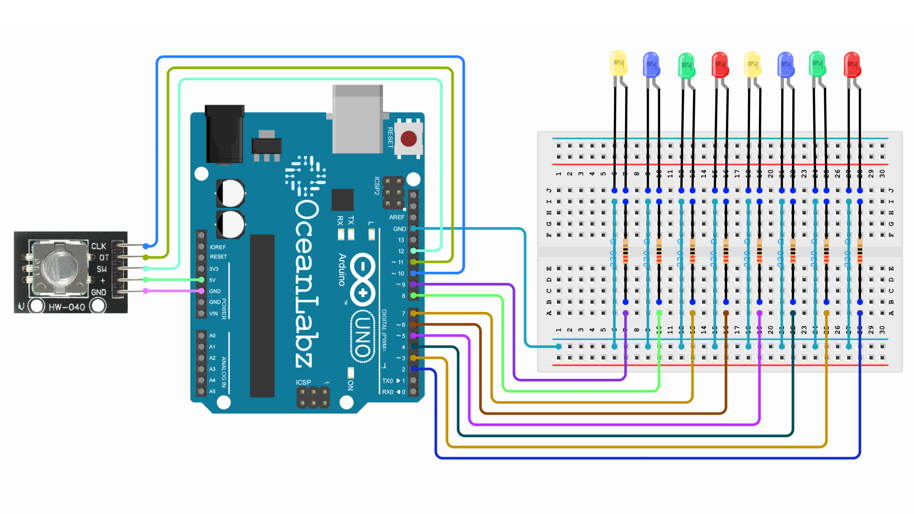
Circuit Diagram / Wiring
- LEDs Wiring:
- Connect 8 LEDs to pins 2, 3, 4, 5, 6, 7, 8, 9 on the Arduino.
- Each LED should have a current-limiting resistor (usually 220Ω to 1kΩ) connected in series with the anode (longer leg), and the cathode (shorter leg) should be connected to GND.
- Rotary Encoder with Arduino:
- ROTARY VCC → 5V (Arduino)
- ROTARY GND → GND (Arduino)
- ROTARY CLK → Pin D10 (Arduino)
- ROTARY DT → Pin D11 (Arduino)
- ROTARY SW → Pin D12 (Arduino)

Arduino Code – Effect 1
Make sure you have the required libraries installed:
- Enocder library for Rotary module.
#include <Encoder.h>

// Define LED pins
const int ledPins[] = {2, 3, 4, 5, 6, 7, 8, 9};

// Define rotary encoder pins
#define CLK 10
#define DT 11
#define SW 12

int counter = 0;

void setup() {
  Serial.begin(9600);

  // Initialize LEDs as output
  for (int i = 0; i < 8; i++) {
    pinMode(ledPins[i], OUTPUT);
  }

  // Initialize rotary encoder pins
  pinMode(CLK, INPUT);
  pinMode(DT, INPUT);
  pinMode(SW, INPUT_PULLUP);
}

void loop() {
  static int lastCLK = HIGH;
  int currentCLK = digitalRead(CLK);

  // Detect rotation
  if (currentCLK == LOW && lastCLK == HIGH) {
    if (digitalRead(DT) == HIGH) {
      counter++;
    } else {
      counter--;
    }
    counter = constrain(counter, 0, 8); // Keep counter between 0 and 8
    updateLEDs();
  }
  lastCLK = currentCLK;

  // Detect button press
  if (digitalRead(SW) == LOW) {
    counter = 0; // Reset counter
    updateLEDs();
    delay(300); // Debounce delay
  }
}

// Function to update LEDs
void updateLEDs() {
  for (int i = 0; i < 8; i++) {
    digitalWrite(ledPins[i], i < counter ? HIGH : LOW);
  }
  Serial.println("LEDs On: " + String(counter));
}
Explanation
- The rotary encoder detects rotation and button presses, incrementing or decrementing the counter based on rotation direction.
- The
countervalue controls how many LEDs are turned on, updating the LEDs in a sequence. - When the encoder button is pressed, the counter resets to 0, turning off all LEDs.
- The code uses
Serial.printto display the number of LEDs currently on for monitoring.
Arduino Code – Effect 2
#include <Encoder.h>

// Define LED pins
const int ledPins[] = {2, 3, 4, 5, 6, 7, 8, 9};

// Define rotary encoder pins
#define CLK 10
#define DT 11
#define SW 12

int counter = 0;
int mode = 0; // Toggle between modes

void setup() {
  Serial.begin(9600);

  // Initialize LEDs as output
  for (int i = 0; i < 8; i++) {
    pinMode(ledPins[i], OUTPUT);
  }

  // Initialize rotary encoder pins
  pinMode(CLK, INPUT);
  pinMode(DT, INPUT);
  pinMode(SW, INPUT_PULLUP);
}

void loop() {
  static int lastCLK = HIGH;
  static int lastSW = HIGH;

  int currentCLK = digitalRead(CLK);
  int currentSW = digitalRead(SW);

  // Detect rotation
  if (currentCLK == LOW && lastCLK == HIGH) {
    if (digitalRead(DT) == HIGH) {
      counter++;
    } else {
      counter--;
    }
    counter = constrain(counter, 0, 7); // Keep counter within LED range
    updateLEDs();
  }
  lastCLK = currentCLK;

  // Detect button press to toggle mode
  if (currentSW == LOW && lastSW == HIGH) {
    mode = !mode; // Toggle between 0 and 1
    counter = 0;  // Reset counter to start from the beginning
    updateLEDs();
    delay(300); // Debounce delay
  }
  lastSW = currentSW;
}

// Function to update LEDs based on mode
void updateLEDs() {
  // Ensure that LEDs turn off if counter exceeds limit
  if (counter > 7) {
    counter = 0; // Reset counter if it exceeds 7
  }

  for (int i = 0; i < 8; i++) {
    if (mode == 0) {
      // Mode 0: LEDs light up one by one cumulatively
      digitalWrite(ledPins[i], i <= counter ? HIGH : LOW);
    } else {
      // Mode 1: Only one LED lights up at a time
      digitalWrite(ledPins[i], i == counter ? HIGH : LOW);
    }
  }
  Serial.println("Mode: " + String(mode) + ", Counter: " + String(counter));
}
Explanation
Rotary Encoder: The rotary encoder rotates to increment or decrement a counter value, controlling the LEDs. It moves through a range of 0 to 7, where each value corresponds to a specific number of LEDs being lit.Mode Toggle: The push button on the rotary encoder toggles between two modes:
- Mode 0: LEDs light up sequentially based on the counter.
- Mode 1: Only one LED lights up at a time based on the counter’s value.
Counter Reset: When the button is pressed, the counter resets to 0, and the LEDs update accordingly. The counter stays between 0 and 7, limiting the range of LED control.LED Control: In each mode, the LEDs are controlled using the digitalWrite() function, turning them on or off based on the counter value and selected mode. The current mode and counter are also printed to the Serial Monitor.


