Index
Introduction
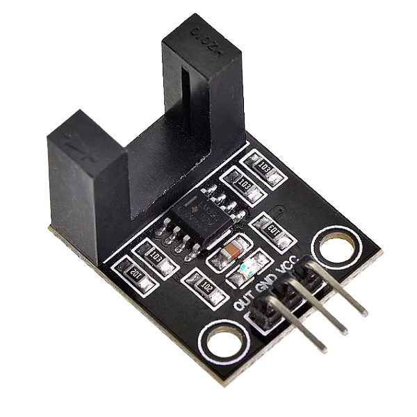
The Infrared Speed Sensor Module is an IR counter that has an IR transmitter and receiver. If any obstacle is placed between these sensors, a signal is sent to the microcontroller. The module can be used in association with a microcontroller for motor speed detection, pulse count, position limit, etc.
Hardware Overview
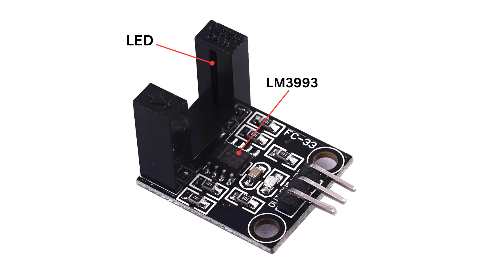
LED (Light Emitting Diode):
- The optointerruptor typically includes an LED that emits infrared (IR) or visible light.
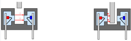
Gap or Interrupter Mechanism:
- There is a physical gap or interrupter between the LED and the phototransistor/photodiode. When this gap is interrupted by an object, it blocks the emitted light from reaching the receiver, causing a change in output.
LM393 Dual Comparators:
- The LM393 IC contains two independent voltage comparators in a single package.
Working Principle
The Infrared Speed Sensor Module has 1 H2010 photocell, which consists of a phototransistor and an infrared light emitter packaged in a 10 cm wide black plastic housing.
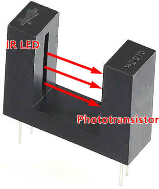
When operating, the infrared light-emitting diode continuously emits infrared light (invisible light), and the photosensitive triode will conduct if it receives it.
Application
- Automotive: Used for vehicle speed detection in speedometers, cruise control systems, and traffic monitoring devices.
- Industrial Automation: Monitoring conveyor belt speed, rotational speed of motors, and production line speed in manufacturing processes.
- Robotics: Implementing obstacle avoidance and motion detection in robotic systems for navigation and collision avoidance.
- Security Systems: Detecting movement and triggering alarms in security systems and automated door openers.
- Sports and Fitness: Measuring speed in athletic training equipment such as treadmills and cycling machines.
- Home Appliances: Controlling the speed of fans and motors based on detected motion or load conditions.
- IoT (Internet of Things): Integrating with IoT devices for smart home automation and monitoring applications.
- Research and Development: Utilizing in experimental setups to measure the speed of rotating or moving objects in laboratory settings.
Technical Specifications
- Operating voltage of 3.3 V to 5 V
- The width of the optical coupling slot: 15mm
- Digital output
- The output valid signal is low.
- It is useful for workpiece counts.
- It’s also useful for industry counting, motor speed testing .
Pinout
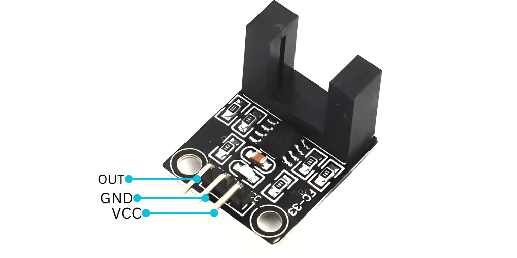
- VCC: Connect to a 5V power supply.
- GND: Connect to ground (0V).
- OUT: Output pin that provides a digital signal (HIGH or LOW) when an object is detected.
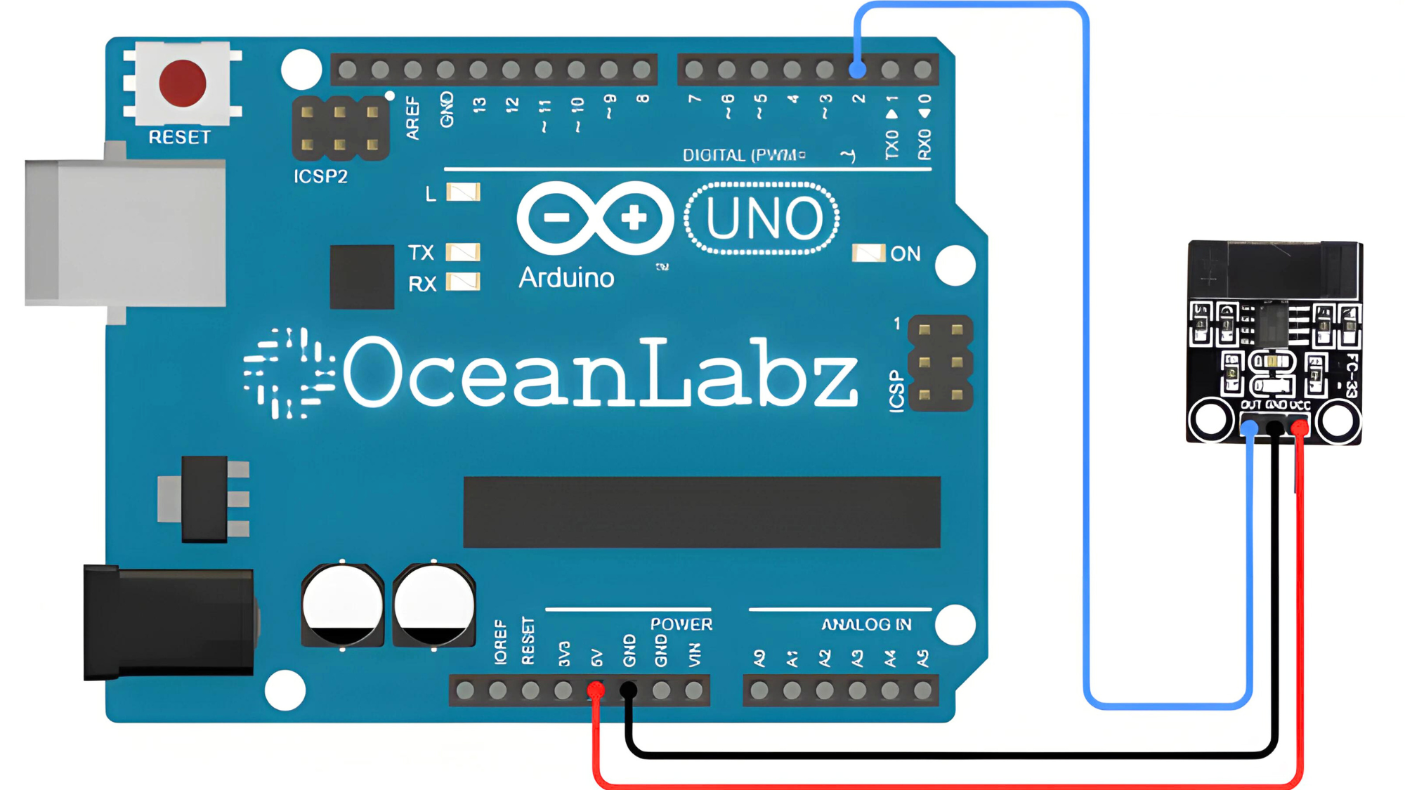
Circuit Diagram
| FC-33 Speed Pin | Arduino Pin |
| VCC | 5 V |
| GND | GND |
| OUT | D2 |
Programming With Arduino
Step 1: Open your first sketch
- Open the Arduino IDE.
- Copy and paste the provided code into a new sketch in the Arduino IDE:
// Define pin connections
#define SENSOR_OUT_PIN 2  // Connect OUT pin of FC-33 sensor to Arduino digital pin 2

void setup() {
  Serial.begin(9600);  // Initialize serial communication
  pinMode(SENSOR_OUT_PIN, INPUT);  // Set SENSOR_OUT_PIN as input
}

void loop() {
  // Read the state of the sensor output
  int sensorValue = digitalRead(SENSOR_OUT_PIN);

  // Print the sensor value (HIGH or LOW) to Serial Monitor
  if (sensorValue == HIGH) {
    Serial.println("Object Detected!");
  } else {
    Serial.println("No Object Detected");
  }

  delay(500);  // Delay for stability
}
Programming With Arduino
Step 1: Open your first sketch
- Open the Arduino IDE.
- Copy and paste the provided code into a new sketch in the Arduino IDE:
Programming With Arduino
Step 1: Open your first sketch
- Open the Arduino IDE.
- Copy and paste the provided code into a new sketch in the Arduino IDE:
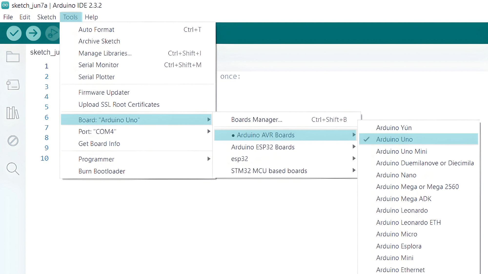
Step 2: Select your board type and port
- Go to Tools > Board and select your Arduino board (e.g., Arduino Uno).
- Go to Tools > Port and select the port to which your Arduino is connected.
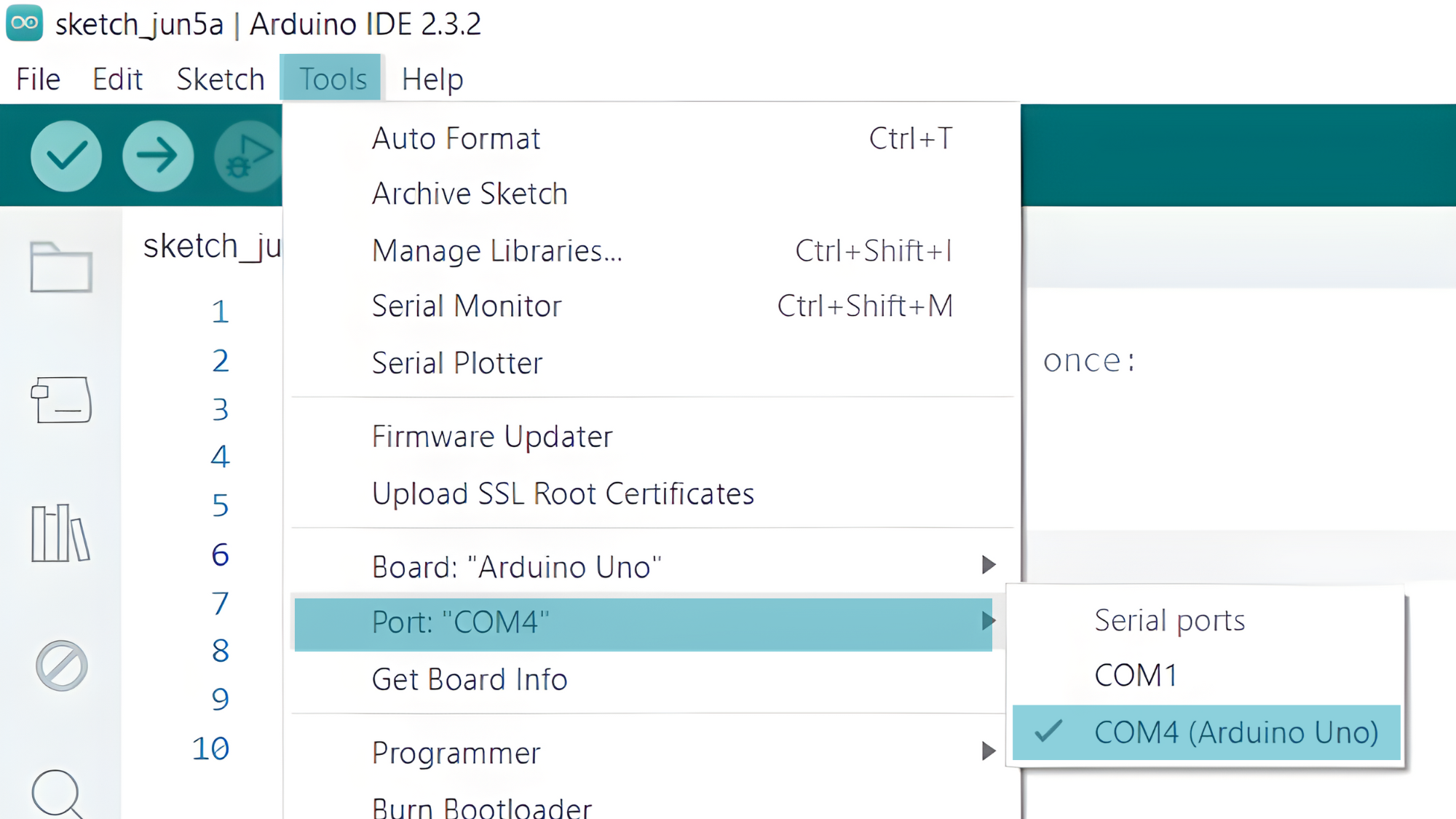
- Verify and upload the code to your Arduino board.

Step 3: Open Serial Monitor:
- Once the code is uploaded successfully, open the Serial Monitor in the Arduino IDE.
- Set the baud rate to 9600 baud.

