Index

Introduction
The 28BYJ-48 is a small stepper motor that is easy to control using an Arduino and the ULN2003 driver. This tutorial will guide you through the wiring and programming needed to control the motor.
Required Components
- Arduino UNO or Nano
- 28BYJ-48 stepper motor
- ULN2003 driver board
- Jumper wires
- Breadboard (optional)
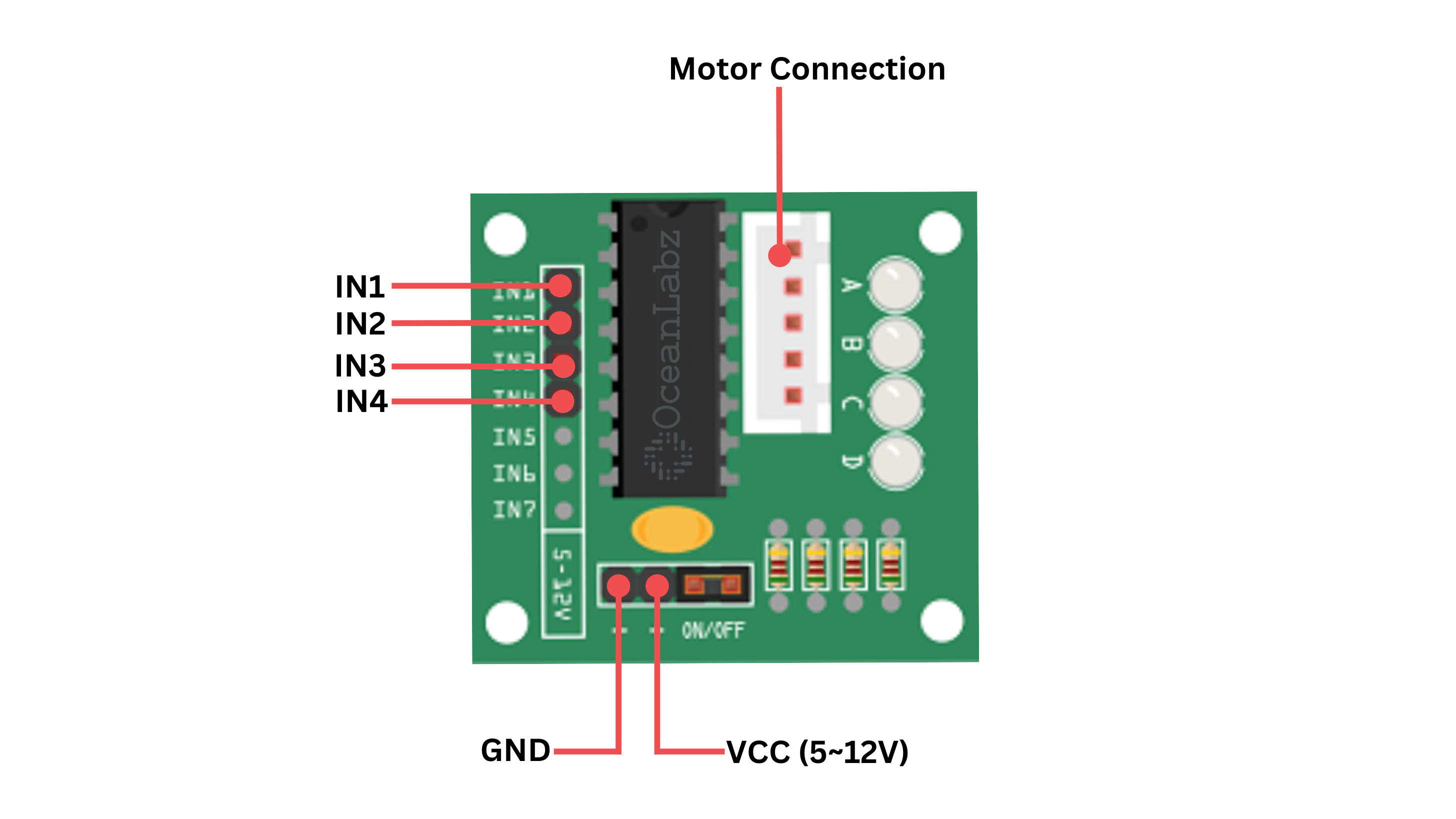
Pinout

Circuit Diagram / Wiring
- ULN2003 VCC → 5V (Arduino)
- ULN2003 GND → GND (Arduino)
- ULN2003 IN1 → Pin D8 (Arduino)
- ULN2003 IN2 → Pin D9 (Arduino)
- ULN2003 IN3 → Pin D10 (Arduino)
- ULN2003 IN4 → Pin D11 (Arduino)

Arduino Code / Programming
Use the following code to control the 28BYJ-48 stepper motor:
#define IN1 8
#define IN2 9
#define IN3 10
#define IN4 11

void setup() {
  pinMode(IN1, OUTPUT);
  pinMode(IN2, OUTPUT);
  pinMode(IN3, OUTPUT);
  pinMode(IN4, OUTPUT);
}

void loop() {
  // Rotate clockwise
  for (int i = 0; i < 512; i++) {
    stepMotor(1);
  }
  delay(1000); // Wait for 1 second

  // Rotate counterclockwise
  for (int i = 0; i < 512; i++) {
    stepMotor(-1);
  }
  delay(1000); // Wait for 1 second
}

void stepMotor(int step) {
  if (step == 1) { // Clockwise
    digitalWrite(IN1, HIGH);
    digitalWrite(IN2, LOW);
    digitalWrite(IN3, LOW);
    digitalWrite(IN4, LOW);
    delay(2);

    digitalWrite(IN1, LOW);
    digitalWrite(IN2, HIGH);
    delay(2);

    digitalWrite(IN2, LOW);
    digitalWrite(IN3, HIGH);
    delay(2);

    digitalWrite(IN3, LOW);
    digitalWrite(IN4, HIGH);
    delay(2);

    digitalWrite(IN4, LOW);
    digitalWrite(IN1, HIGH);
    delay(2);
  } else if (step == -1) { // Counterclockwise
    digitalWrite(IN4, HIGH);
    digitalWrite(IN3, LOW);
    digitalWrite(IN2, LOW);
    digitalWrite(IN1, LOW);
    delay(2);

    digitalWrite(IN4, LOW);
    digitalWrite(IN3, HIGH);
    delay(2);

    digitalWrite(IN3, LOW);
    digitalWrite(IN2, HIGH);
    delay(2);

    digitalWrite(IN2, LOW);
    digitalWrite(IN1, HIGH);
    delay(2);

    digitalWrite(IN1, LOW);
    digitalWrite(IN4, HIGH);
    delay(2);
  }
}
Explanation of the Code
- Pin Definitions: Define the pins connected to the ULN2003 driver.
- Setup Function: Set the defined pins as outputs.
- Loop Function: The motor rotates 512 steps clockwise, pauses for one second, then rotates 512 steps counterclockwise.
- Step Motor Function: This function controls the motor by activating the appropriate pins in sequence.
Arduino Projects:
Arduino Project 1 – Rotary Encoder-Controlled Stepper Motor
This project uses a rotary encoder to control a stepper motor via a ULN2003 driver. The encoder detects rotation direction and adjusts the motor’s movement. The motor moves clockwise or counterclockwise based on the encoder’s input. This setup allows precise control in applications like robotics and motion systems.
Required Components
- Arduino UNO or Nano
- Rotary Encoder
- 28BYJ-48 stepper motor
- ULN2003 driver board
- Jumper wires
- Breadboard (optional)
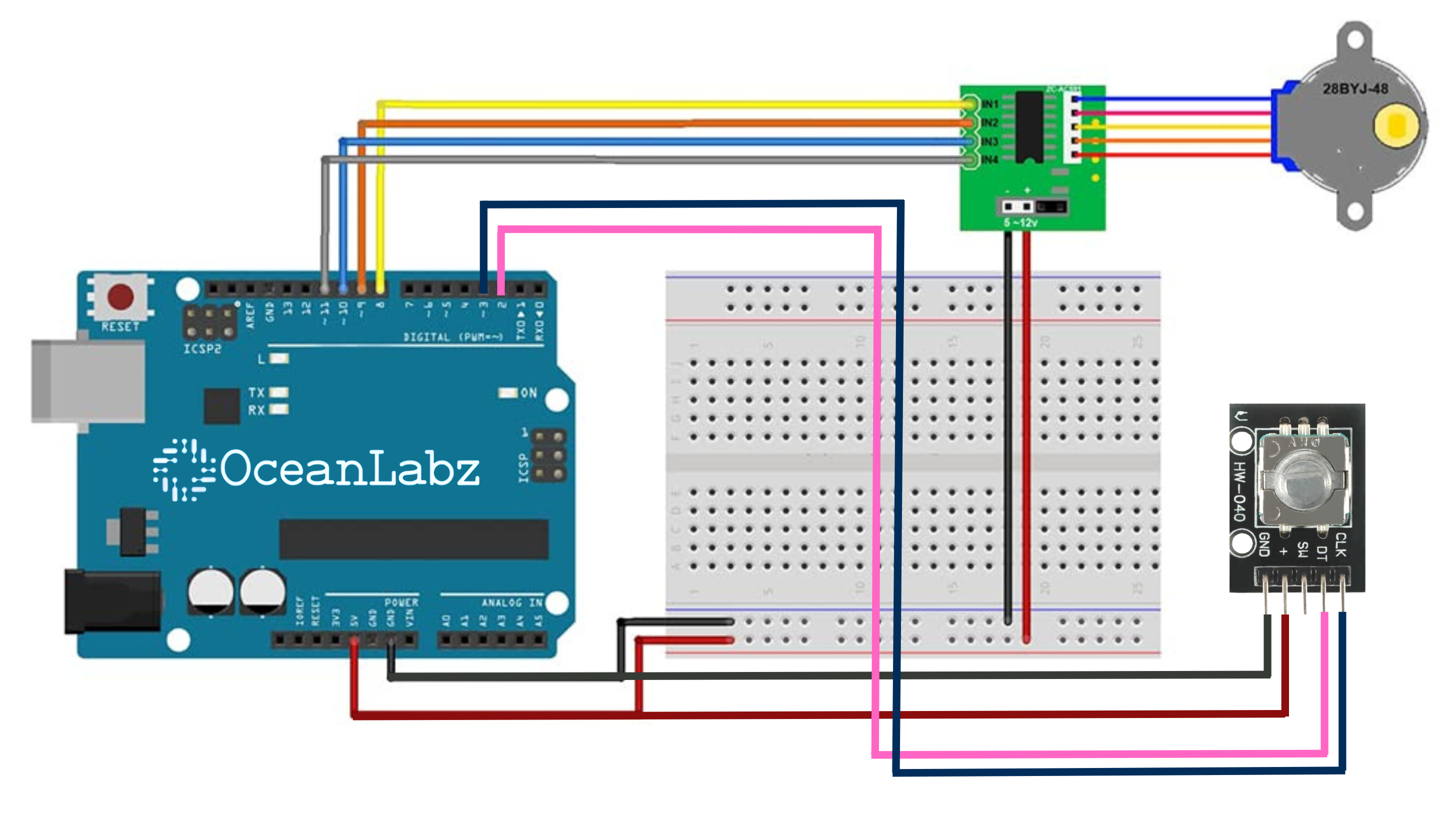
Circuit Diagram / Wiring
- ULN2003
- ULN2003 VCC → 5V (Arduino)
- ULN2003 GND → GND (Arduino)
- ULN2003 IN1 → Pin D8 (Arduino)
- ULN2003 IN2 → Pin D9 (Arduino)
- ULN2003 IN3 → Pin D10 (Arduino)
- ULN2003 IN4 → Pin D11 (Arduino)
- Rotary Encoder
- VCC (Rotary) → 5V (Arduino)
- GND (Rotary) → GND (Arduino)
- CLK (Rotary) → Pin D3 (Arduino)
- DT (Rotary) → Pin D2 (Arduino)

Arduino Code
#define IN1 8
#define IN2 9
#define IN3 10
#define IN4 11

const int encoderPinA = 2;  // Encoder A pin
const int encoderPinB = 3;  // Encoder B pin

int lastEncoderState = LOW;
int encoderPosition = 0;

void setup() {
  // Initialize pins for stepper motor control
  pinMode(IN1, OUTPUT);
  pinMode(IN2, OUTPUT);
  pinMode(IN3, OUTPUT);
  pinMode(IN4, OUTPUT);

  // Initialize rotary encoder pins
  pinMode(encoderPinA, INPUT);
  pinMode(encoderPinB, INPUT);

  // Start the serial communication
  Serial.begin(9600);  // Set the baud rate for serial communication
}

void loop() {
  int encoderState = digitalRead(encoderPinA);

  // Check for a change in the encoder state
  if (encoderState != lastEncoderState) {
    // Determine direction based on the second pin state
    if (digitalRead(encoderPinB) != encoderState) {
      encoderPosition++;  // Clockwise rotation
    } else {
      encoderPosition--;  // Counterclockwise rotation
    }

    // Print encoder position to the serial monitor
    Serial.print("Encoder Position: ");
    Serial.println(encoderPosition);

    // Control motor movement based on encoder position
    if (encoderPosition > 0) {
      stepMotor(1);  // Move motor clockwise
      Serial.println("Motor: Clockwise");
    } else if (encoderPosition < 0) {
      stepMotor(-1);  // Move motor counterclockwise
      Serial.println("Motor: Counterclockwise");
    }

    // Optionally reset the encoder position after movement
    encoderPosition = 0;
  }

  // Store the current encoder state for the next loop
  lastEncoderState = encoderState;
}

// Function to control stepper motor movement
void stepMotor(int step) {
  if (step == 1) {  // Clockwise
    digitalWrite(IN1, HIGH);
    digitalWrite(IN2, LOW);
    digitalWrite(IN3, LOW);
    digitalWrite(IN4, LOW);
    delay(5);  // Reduced delay for increased speed

    digitalWrite(IN1, LOW);
    digitalWrite(IN2, HIGH);
    delay(5);

    digitalWrite(IN2, LOW);
    digitalWrite(IN3, HIGH);
    delay(5);

    digitalWrite(IN3, LOW);
    digitalWrite(IN4, HIGH);
    delay(5);

    digitalWrite(IN4, LOW);
    digitalWrite(IN1, HIGH);
    delay(5);
  } else if (step == -1) {  // Counterclockwise
    digitalWrite(IN4, HIGH);
    digitalWrite(IN3, LOW);
    digitalWrite(IN2, LOW);
    digitalWrite(IN1, LOW);
    delay(5);

    digitalWrite(IN4, LOW);
    digitalWrite(IN3, HIGH);
    delay(5);

    digitalWrite(IN3, LOW);
    digitalWrite(IN2, HIGH);
    delay(5);

    digitalWrite(IN2, LOW);
    digitalWrite(IN1, HIGH);
    delay(5);

    digitalWrite(IN1, LOW);
    digitalWrite(IN4, HIGH);
    delay(5);
  }
}
Explanation
- Rotary encoder detects rotation via
encoderPinAandencoderPinBto update position. - Stepper motor control is managed using pins
IN1toIN4. stepMotor()function moves the motor clockwise or counterclockwise based on encoder input.- Serial Monitor displays encoder position and motor direction for feedback.
Testing and Troubleshooting
- Check Connections: Ensure all connections are secure.
- Power Supply: Make sure the motor is powered by the Arduino or an external power source.
- Adjust Delays: You can modify the delay in the
stepMotorfunction to change the speed of rotation.


