Index
Introduction
A water level sensor is an electronic device used to measure and indicate the level of water in a container or tank. It is commonly employed in various applications such as water management systems, industrial processes, and home appliances.
Working principle
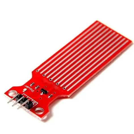
The working of the water level sensor is pretty simple and easy to understand. The PCB is made out of long conductive plates. When the water reaches a certain level the conductivity between the two plates changes, and by measuring the changes we can measure the water level.
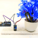
The above Gif shows the working of the water level sensor in action. As you can see when the drop of water falls inside the glass, the water level rises and the voltage on the output pin also rises. This phenomenon is directly proportional to the output voltage. This happens because the sensor portion on the PCB is made out of 10 conducting plates, 5 of which are power tracks and 5 others are the sensor tracks.
Application
- Smart Home Automation:
- Agricultural Irrigation Systems:
- Industrial Tank Monitoring:
- Flood Monitoring and Early Warning Systems:
- Wastewater Treatment Plants:
Technical Specifications
- Range: Measures water levels within a specified range (e.g., 0-2 meters).
- Accuracy: Indicates how closely readings match actual water levels (e.g., ±1%).
- Output: Provides analog voltage, digital signal, or current loop output.
- Power: Requires specific voltage or current (e.g., 5V DC, 4-20 mA).
- Temperature Range: Works reliably within defined temperature limits (e.g., -20°C to 80°C).
- Material: Compatible with specific materials (e.g., stainless steel, PVC).
- IP Rating: Indicates protection against dust and water ingress (e.g., IP67).
- Response Time: Time taken to detect and respond to water level changes (e.g., <100 ms).
- Mounting: Installation method (e.g., threaded, flanged, submersible).
Pinout

- VCC: Connect to 3.3V or 5V for power.
- GND: Connect to ground (0V).
- OUT: Connect to analog A0.
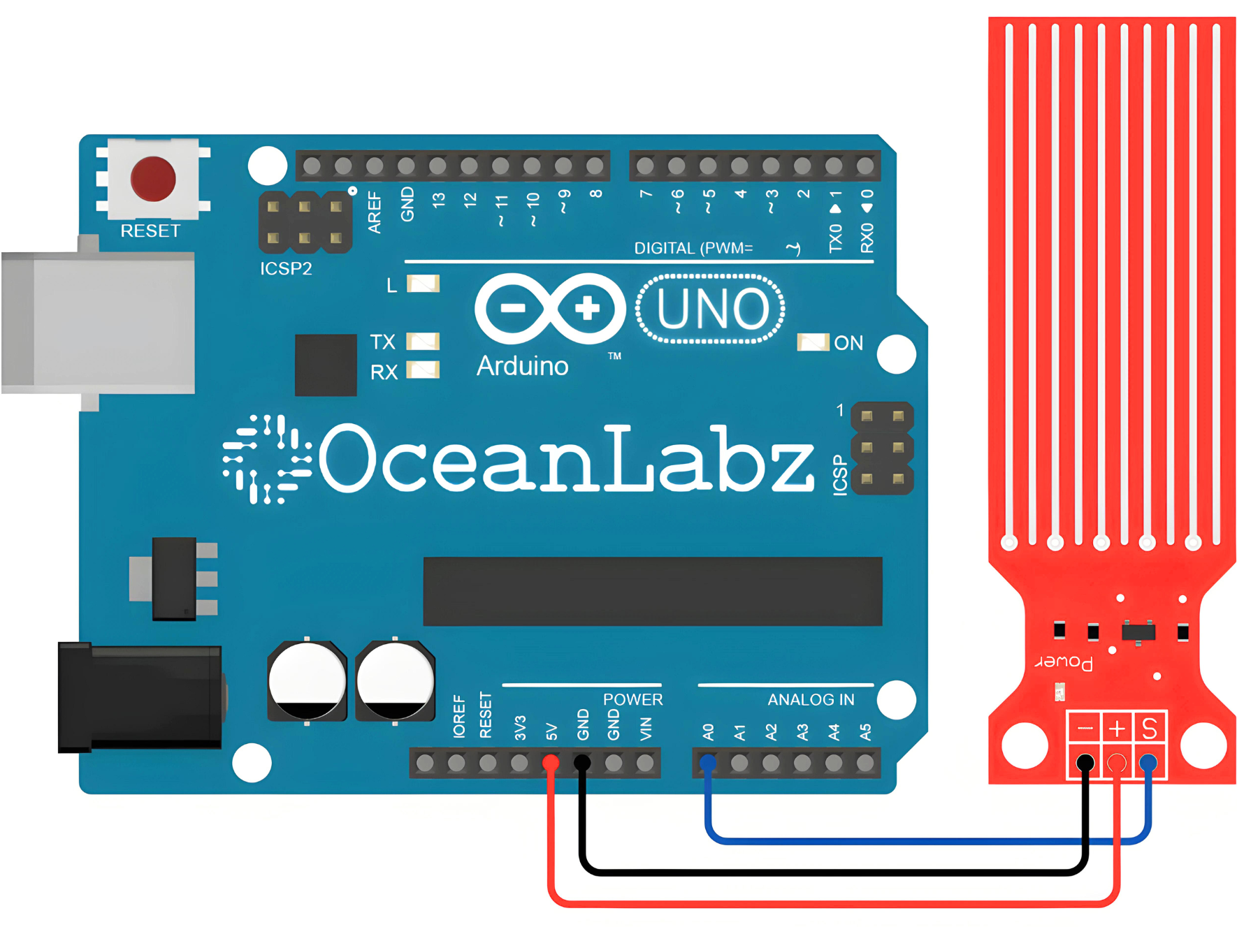
Circuit Diagram
| Water Sensor Pin | Arduino Pin |
| VCC | 5 V |
| GND | GND |
| OUT | Analog A0 |
Programming With Arduino
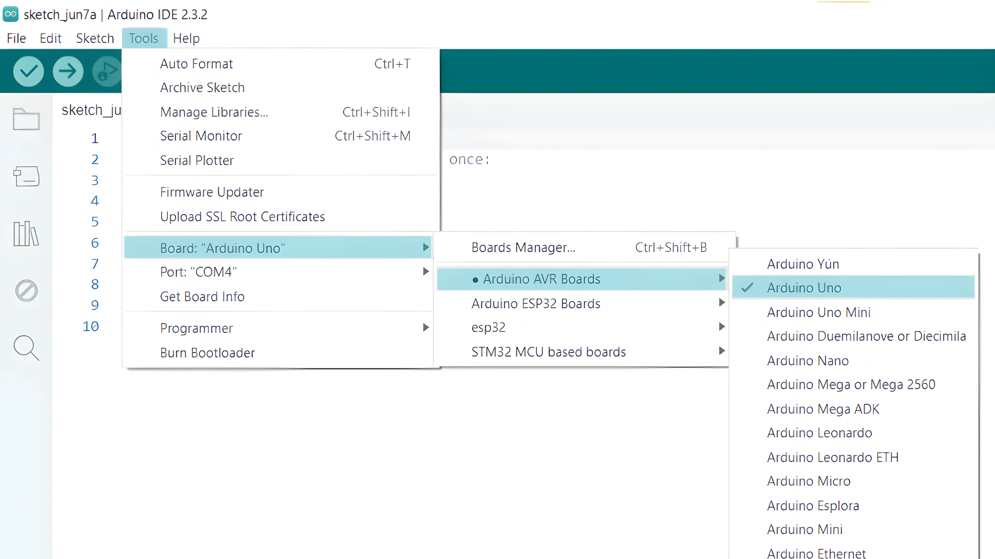
Step 1: Select the appropriate board and port
- Go to Tools > Board and select your Arduino board (e.g., Arduino Uno).
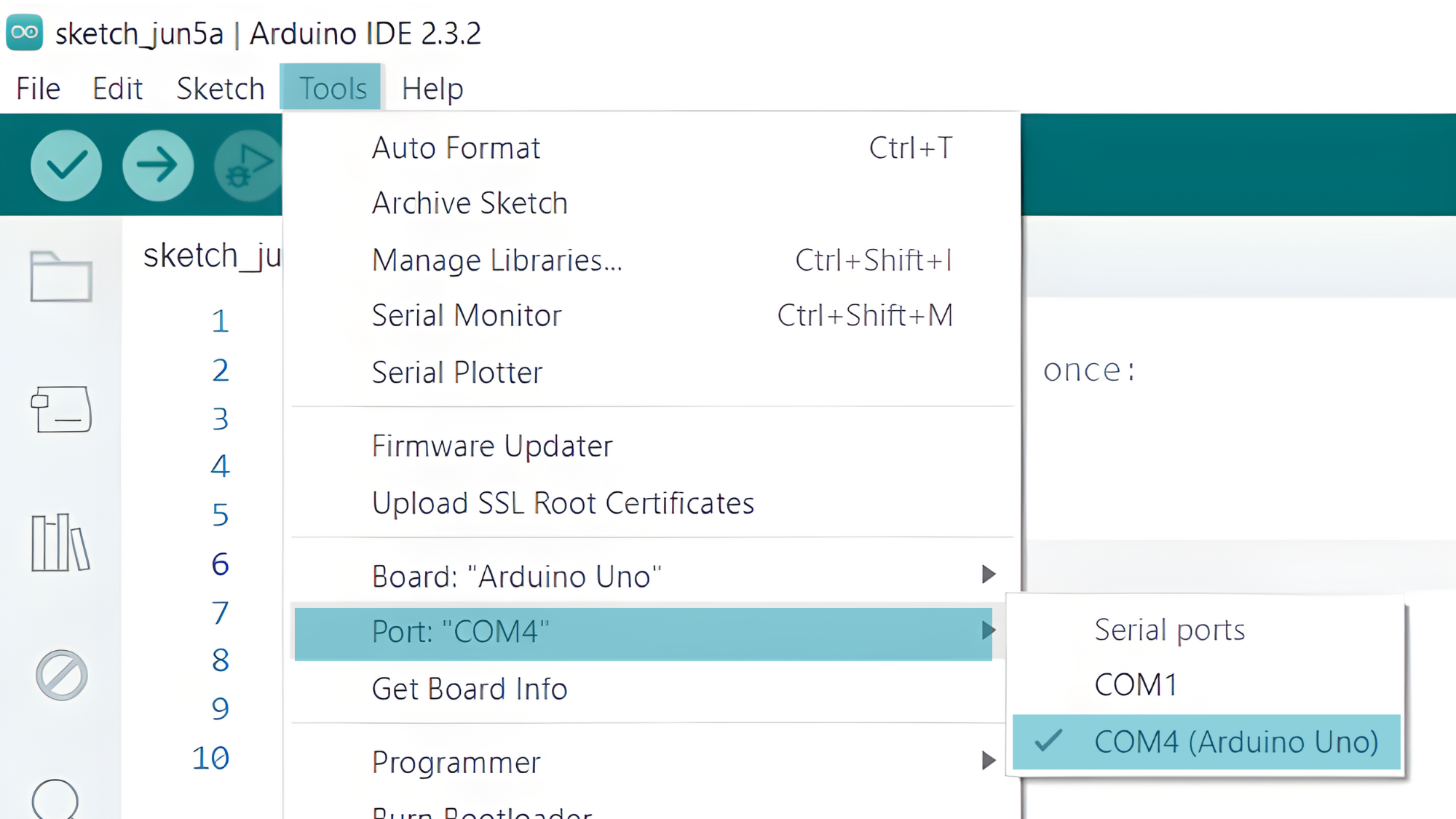
- Go to Tools > Port and select the port to which your Arduino is connected.
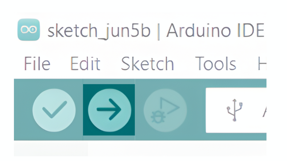
Step 3: Upload the Code
- Copy the provided code into your Arduino IDE.
const int sensorPin = A0;
int sensorValue = 0;
int waterLevel = 0;

void setup() {
  Serial.begin(9600);
}

void loop() {
  sensorValue = analogRead(sensorPin);
  waterLevel = map(sensorValue, 0, 1023, 0, 100); // Adjust the mapping range as needed
  Serial.print("Water Level: ");
  Serial.print(waterLevel);
  Serial.println("%");
  delay(1000);
}
- Verify and upload the code to your Arduino board.
Step 4: Open the Serial Monitor
- Connect your Arduino to the computer and upload the code.
- Open the Serial Monitor in the Arduino IDE by going to Tools > Serial Monitor or pressing
Ctrl+Shift+M. - Set the baud rate to 9600 in the Serial Monitor.