Index
Introduction

This module typically consists of an IR transmitter (IR LED) and an IR receiver (photodiode). It emits infrared light and detects the reflection of that light. When an obstacle is detected, the reflected light intensity changes, indicating the presence of an obstacle.
Hardware Overview
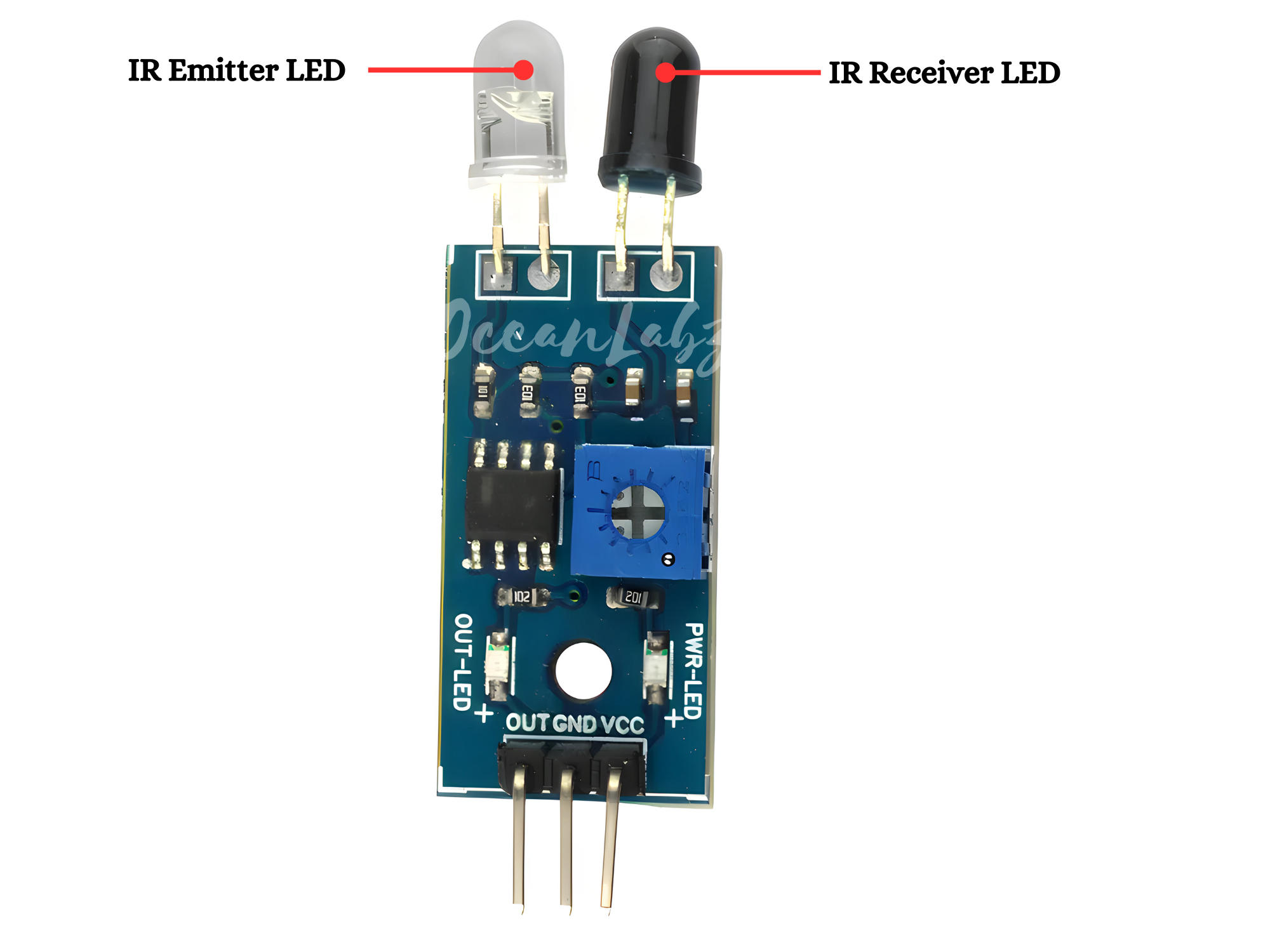
Receiver LED: The “receiver LED” of the IR Infrared Obstacle Avoidance Sensor is not a distinct component but rather refers to the infrared receiver sensor integrated into the sensor module. This sensor detects infrared light reflected back from obstacles in its detection range, enabling the sensor to determine the presence or absence of obstacles based on the intensity and timing of the received infrared signals.
Emitter LED: It’s a crucial component of the IR Infrared Obstacle Avoidance Sensor, emitting infrared light pulses that bounce off obstacles in its path. These reflected pulses are then detected by the sensor’s receiver. This process helps the sensor determine the presence or absence of obstacles in its detection range, enabling applications like obstacle detection, object tracking, and more.

Comparator Circuit: The sensor includes a comparator circuit that compares the voltage level of the signal from the photodiode with a reference voltage. When an obstacle is detected, the voltage level changes, triggering the comparator to output a digital signal indicating the presence of an obstacle.
Potentiometer: Some IR obstacle avoidance sensors come with a potentiometer that allows you to adjust the sensitivity of the sensor. This enables you to customize the detection range according to your requirements.

The output LED: on an IR Infrared Obstacle Avoidance Sensor typically indicates the detection of an obstacle. When the sensor detects an object within its detection range, it triggers the output LED to illuminate, providing a visual indication of obstacle detection. This LED is often labeled on the sensor module and serves as a helpful indicator during operation.
The power LED: on an IR Infrared Obstacle Avoidance Sensor indicates that the sensor module is receiving power. When the sensor is properly connected and powered, the power LED will illuminate, providing a visual indication that the sensor is operational. This LED helps users confirm that the sensor is receiving power and ready for use.
Working Principle
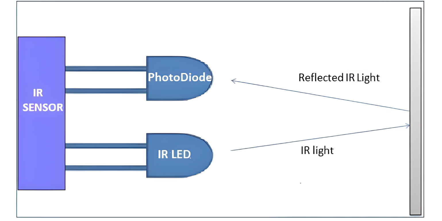
An IR sensor consists of two parts, the emitter circuit, and the receiver circuit. This is collectively known as a photo-coupler or an optocoupler.
The emitter is an IR LED and the detector is an IR photodiode. The IR photodiode is sensitive to the IR light emitted by an IR LED. The photodiode’s resistance and output voltage change in proportion to the IR light received. This is the underlying working principle of the IR sensor.
The type of incidence can be direct incidence or indirect incidence. In direct incidence, the IR LED is placed in front of a photodiode with no obstacle.
In indirect incidence, both the diodes are placed side by side with an opaque object in front of the sensor. The light from the IR LED hits the opaque surface and reflects back to the photodiode.
Application
- Robotics
- Proximity Sensing
- Interactive Installations
- Industrial Automation
- Home Automation
- Educational Projects
Technical Specifications
- Operating voltage 5v DC
- I/O pins are 5V and 3.3V compliant
- Range: Up to 20cm
- Adjustable Sensing range
- Built-in Ambient Light Sensor
- 20mA supply current
- Mounting hole
Pinout

- VCC: Connect this pin to the positive voltage supply (usually 3.3V to 5V).
- GND: Connect this pin to the ground (0V) of the power supply.
- OUT: This pin provides a digital output signal (HIGH or LOW) indicating the presence of an obstacle
Circuit Diagram
| IR Pin | Arduino Pin |
| VCC | 5 V |
| GND | GND |
| OUT | D2 |

Programming With Arduino
Step 1: Select the appropriate board and port
Go to Tools > Board and select your Arduino board (e.g., Arduino Uno).

Go to Tools > Port and select the port to which your Arduino is connected.

Step 2: Upload the Code
- Copy the provided code into your Arduino IDE.
#define IR_PIN 2 // Define the pin connected to the sensor module

void setup() {
  pinMode(IR_PIN, INPUT); // Set the sensor pin as an input
  Serial.begin(9600); // Initialize serial communication
}

void loop() {
  int obstacleDetected = digitalRead(IR_PIN); // Read the sensor value

  if (obstacleDetected == HIGH) {
    Serial.println("Obstacle detected!"); // Print message if obstacle is detected
  } else {
    Serial.println("No obstacle detected"); // Print message if no obstacle is detected
  }

  delay(500); // Delay for stability
}
- Verify and upload the code to your Arduino board.

Step 3: Monitor the Output
Open the serial monitor in the Arduino IDE. You should see messages indicating whether an obstacle is detected or not.
Step 4: Test the Sensor
Place objects in front of the sensor and observe the output on the serial monitor. The sensor should detect obstacles and print appropriate messages.

