Index
Introduction
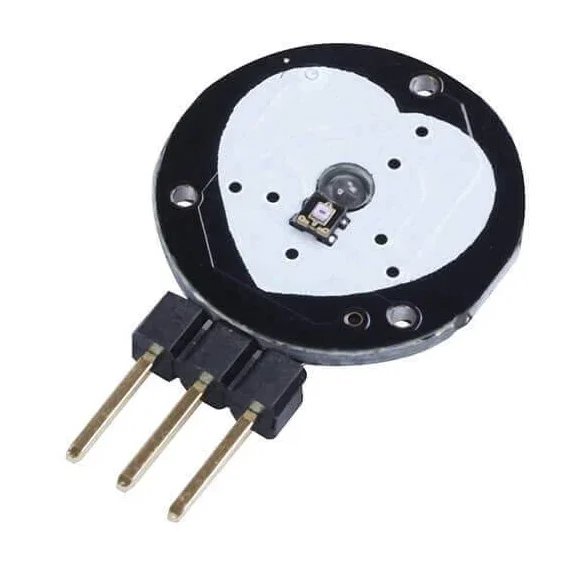
A pulse sensor is a device used to measure heart rate by detecting changes in blood volume in a fingertip. It typically includes an infrared LED and a photodetector to capture the pulsatile signal caused by the heartbeats. When placed on a finger, the sensor illuminates the skin and detects variations in light absorption due to blood flow, allowing the Arduino to process this data and calculate the heart rate. This technology is commonly used in wearable health monitoring devices and DIY projects for real-time heart rate measurement and analysis.
Working Principle
The Pulse Sensor works on the principle of Photoplethysmography (PPG), which is a non-invasive method for measuring changes in blood volume under the skin. The sensor essentially consists of two main components: a light-emitting diode (LED) that shines light into the skin and a photodetector that measures the amount of light that is reflected back. Here’s a detailed explanation of its working:
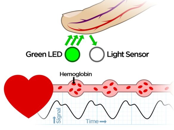
- Light Emission: A green LED emits light into the skin.
- Reflection & Detection: The light interacts with blood and is partially reflected back, captured by a photodetector.
- Heart Rate: Changes in reflected light create a waveform that correlates with heartbeats.
- Oxygen Level: The amount of reflected light also indicates blood oxygen levels, as oxygenated blood absorbs more green light.
- Signal Filtering: A Low Pass Filter cleans up the noisy, raw signal from the photodetector.
- Amplification: An operational amplifier boosts the filtered signal for better accuracy.
- Data Reading: Finally, an Arduino reads the amplified signal and software algorithms translate it into heart rate and potentially blood oxygen levels.
Application
- Wearable health devices
- Medical monitoring
- Sports and fitness applications
- Biofeedback systems
- Research studies
- DIY electronics projects
- Educational demonstrations
Technical Specifications
- Power Supply: 3.3V – 5V DC
- Supply Current: less than 4mA.
- Measurement Type: Photoplethysmography (PPG)
- LED: Kingbright Reverse Mounted Green LED
- Ambient Light Sensor: APDS-9008 from Avago
- Operational Amplifier: MCP6001 from Microchip
- Dimensions: 20mm diameter and 5mm thickness
Pinout
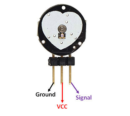
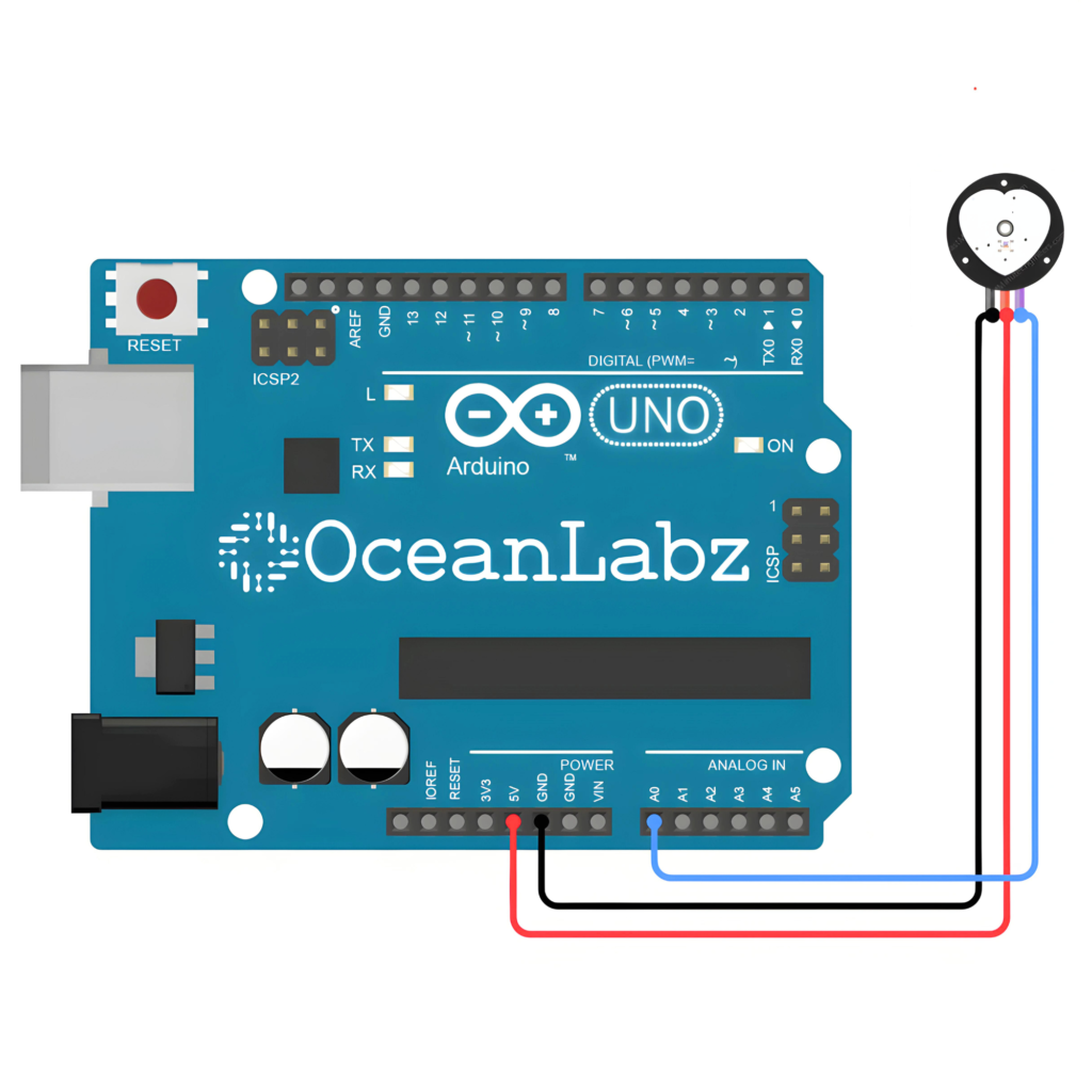
- Pulse Sensor VCC -> Arduino 5V
- Pulse Sensor GND -> Arduino GND
- Pulse Sensor OUT -> Arduino A0
Circuit Diagram
| Pulse Sensor Pin | Arduino Pin |
| VCC | 5 V |
| GND | GND |
| OUT | Analog A0 |
Programming With Arduino
Step 1: Open your first sketch
- Open the Arduino IDE.
- Copy and paste the provided code into a new sketch in the Arduino IDE:
const int pulseSensorPin = A0;

void setup() {
  Serial.begin(9600);
}

void loop() {
  int sensorValue = analogRead(pulseSensorPin);

  Serial.println(sensorValue);

  delay(10); // Adjust delay time as needed
}
Step 2: Select your board type and port
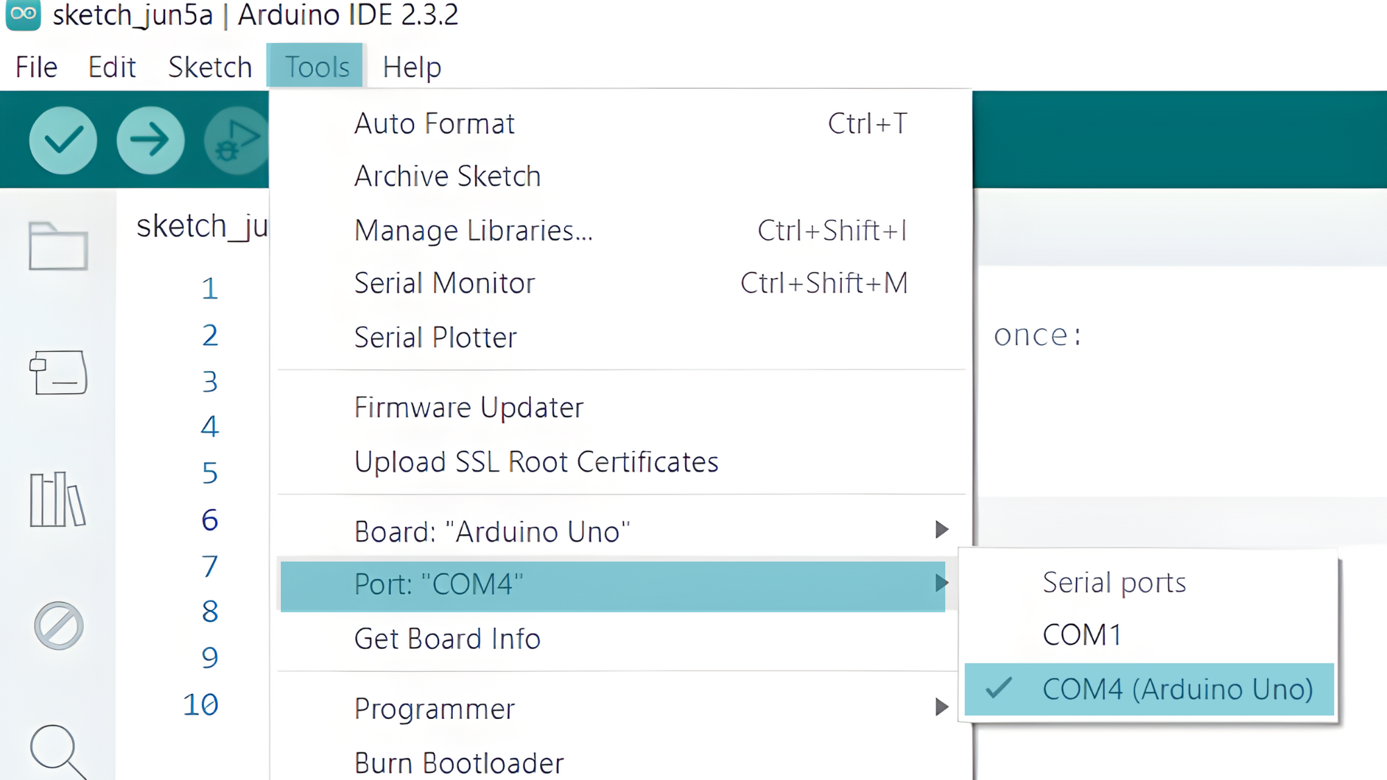
- Go to Tools > Board and select your Arduino board (e.g., Arduino Uno).

- Go to Tools > Port and select the port to which your Arduino is connected.
- Verify and upload the code to your Arduino board.

Step 3: Open Serial Monitor:
- Once the code is uploaded successfully, open the Serial Monitor in the Arduino IDE.
- Set the baud rate to 9600 baud.
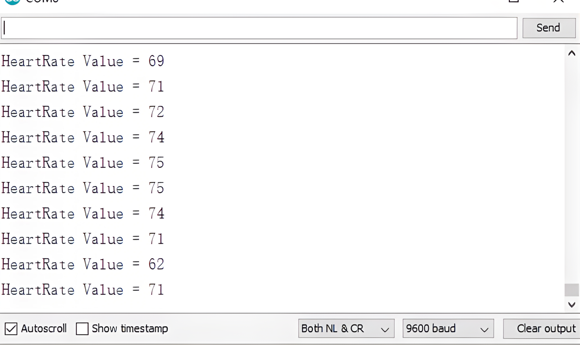
- You should see distance measurements in centimeters printed in the Serial Monitor.
