Index
Introduction

RFID (Radio Frequency Identification) is a technology that uses radio waves to automatically identify and track objects equipped with RFID tags. These tags contain unique identifiers and can be passive (powered by the reader’s signal) or active (with their own power source). RFID systems consist of readers that emit radio waves and antennas to communicate with tags. When a tag enters the reader’s range, it responds by transmitting its stored information back to the reader. RFID is widely used for supply chain management, inventory tracking, access control, and other applications where automatic identification and tracking of objects are required. It provides a convenient and efficient way to enhance operational processes and security across various industries.
Hardware Overview
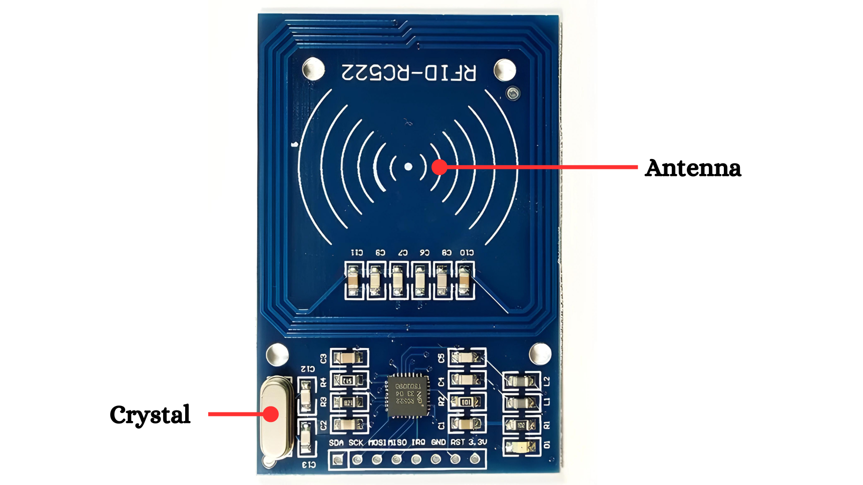
Antenna:
- Function: The antenna in both the RFID reader and tag is critical for transmitting and receiving radio signals. It converts electrical signals from the RFID reader into radio waves and vice versa.
- Design: Typically a coil of wire that generates a magnetic field when an electrical current passes through it. The design and size of the antenna affect the range and efficiency of the RFID system.
- Placement: Must be correctly aligned to ensure optimal communication between the reader and tags.
Crystal Oscillator in RFID Systems:
- A crystal oscillator in RFID systems ensures precise timing for the transmission and reception of radio signals, maintaining a stable frequency reference for the system’s operations. This is crucial for accurate and reliable communication between the RFID reader and tags.

Microcontroller:
- Processing Unit: Manages data from the MFRC522 IC and performs necessary computations.
- Memory: Stores data and program code.
- I/O Interfaces: Connects to other devices and peripherals, including the MFRC522 IC via SPI.
- Power Management: Handles power supply and distribution to various components.
Power LED:
- Indication: Shows that the RFID reader is powered on and operational.
- Location: Usually placed on the RFID reader module.
- Status: Lit when the device is connected to a power source.
Working Principle
An RFID or radio frequency identification system consists of two main components, a tag attached to the object to be identified, and a reader that reads the tag.
A reader consists of a radio frequency module and an antenna that generates a high frequency electromagnetic field. Whereas the tag is usually a passive device (it does not have a battery). It consists of a microchip that stores and processes information, and an antenna for receiving and transmitting a signal.
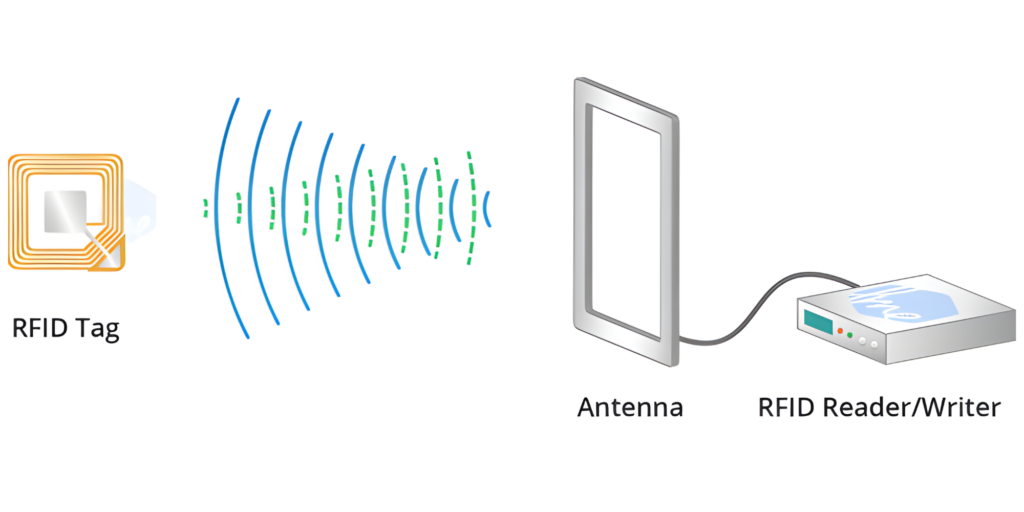
When the tag is brought close to the reader, the reader generates an electromagnetic field. This causes electrons to move through the tag’s antenna and subsequently powers the chip.
Application
- pet and livestock tracking.
- inventory management.
- asset tracking and equipment tracking.
- inventory control.
- cargo and supply chain logistics.
- vehicle tracking.
- customer service and loss control.
- improved visibility and distribution in the supply chain.
Technical Specification
The MFRC522 is a highly integrated reader/writer IC for contactless communication at 13.56 MHz. It supports ISO/IEC 14443 A/MIFARE and NTAG.
Here are the technical specifications of the MFRC522:
- Supply Voltage: 2.5 V to 3.3 V
- Operating Frequency: 13.56 MHz
- Supported Communication Interfaces: SPI, I2C, UART
- Operating Temperature Range: -25°C to +85°C
- Logic inputs : 5V Tolerent
- Max. Operating Current: 13-26mA
- Read Range: 5 cm
Pinout
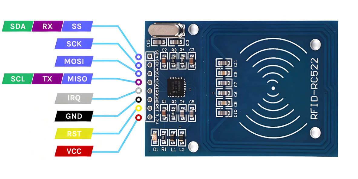
- VCC: Connected to 3.3V or 5V on Arduino
- GND: Connected to GND on Arduino
- SDA: Connected to Arduino’s digital pin 10
- SCK: Connected to Arduino’s digital pin 13 (SCK)
- MOSI: Connected to Arduino’s digital pin 11 (MOSI)
- MISO: Connected to Arduino’s digital pin 12 (MISO)
- NSS (SS): Connected to any digital pin (e.g., pin 9)
- RST: Connected to any digital pin (e.g., pin 8)
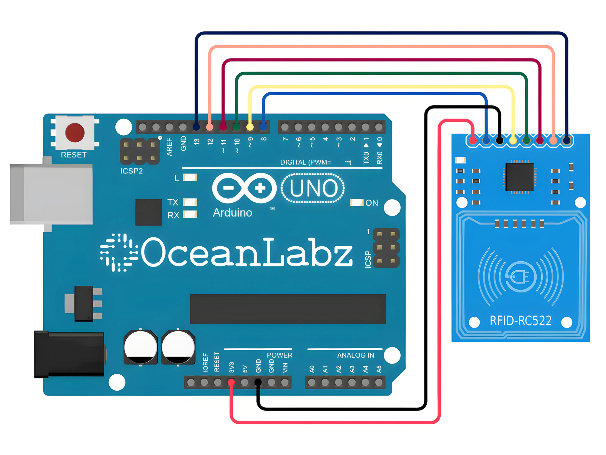
Circuit Description
| RFID Pin | Arduino Pin |
| VCC (3.3v) | 5 V |
| GND | GND |
| SDA | D10 |
| SCK | D13 |
| MOSI | D11 |
| MISO | D12 |
| NSS | D9 |
| RST | D8 |
Programming With Arduino
Step 1: Open your first sketch
- Open the Arduino IDE.
- Copy and paste the provided code into a new sketch in the Arduino IDE:
#include <SPI.h>
#include <MFRC522.h>

#define RST_PIN         8
#define SS_PIN          10

MFRC522 mfrc522(SS_PIN, RST_PIN);  // Create MFRC522 instance

void setup() {
  Serial.begin(9600);		// Initialize serial communications with the PC
  while (!Serial);		// Do nothing if no serial port is opened (added for Arduinos based on ATMEGA32U4)
  SPI.begin();			// Init SPI bus
  mfrc522.PCD_Init();		// Init MFRC522
  delay(4);				// Optional delay. Some board do need more time after init to be ready, see Readme
  mfrc522.PCD_DumpVersionToSerial();	// Show details of PCD - MFRC522 Card Reader details
  Serial.println(F("Scan PICC to see UID, SAK, type, and data blocks..."));
}

void loop() {
  // Reset the loop if no new card present on the sensor/reader. This saves the entire process when idle.
  if ( ! mfrc522.PICC_IsNewCardPresent()) {
    return;
  }

  // Select one of the cards
  if ( ! mfrc522.PICC_ReadCardSerial()) {
    return;
  }

  // Dump debug info about the card; PICC_HaltA() is automatically called
  mfrc522.PICC_DumpToSerial(&(mfrc522.uid));
}
Step 2: Install the Required Library
- Go to Sketch > Tools> Manage Libraries.
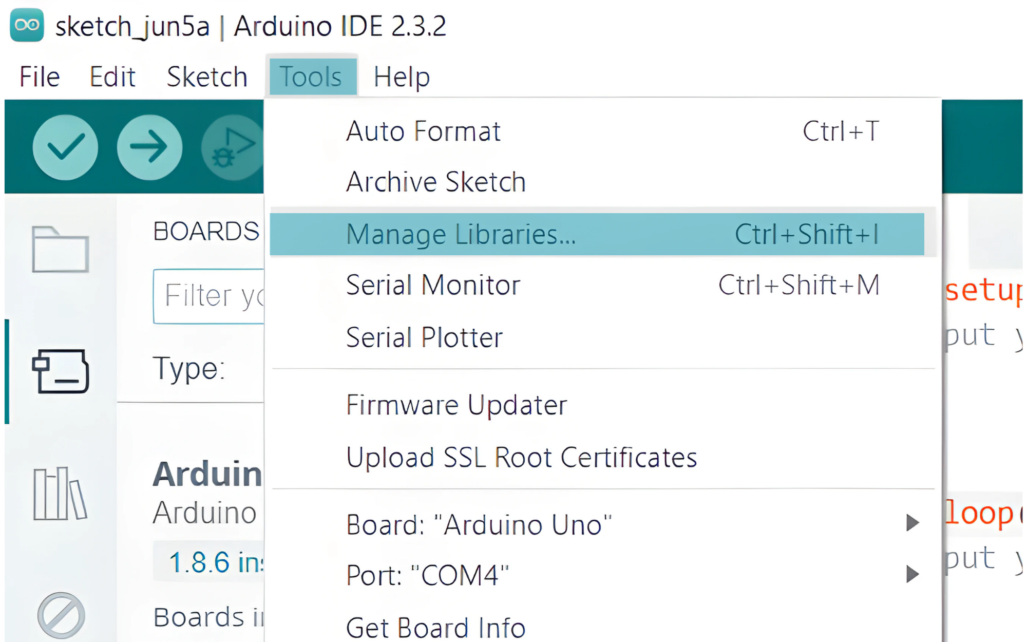
- Search for MFRC522 and install the library by GithubCommunity.

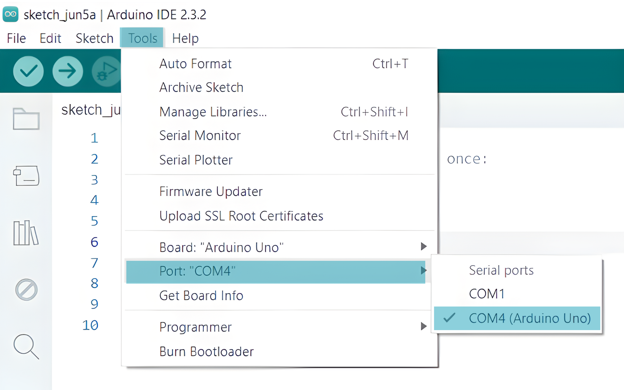
Step 3: Select your board type and port
- In the Arduino IDE, select your Arduino board from
Tools>Board.

Select the serial device of the board from the Tools | Serial Port menu. This is likely to be COM4 or higher (COM1 and COM2 are usually reserved for hardware serial ports). To find out, you can disconnect your board and re-open the menu; the entry that disappears should be the Arduino board. Reconnect the board and select that serial port.
Step 4: Upload the Sketch
- Click the “Upload” button (right arrow icon) to upload the sketch to the Arduino.

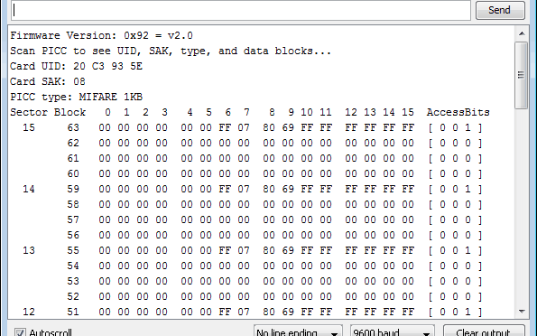
Step 5: Open Serial Monitor
- After uploading the code, open the Serial Monitor from the Tools menu or press Ctrl+Shift+M.
- Set the baud rate to 9600.